Displacement control valve for variable displacement compressor

a variable-discharge compressor and displacement control technology, which is applied in the direction of machines/engines, multi-cylinder pumps, and positive-discharge liquid engines, etc., can solve the problems of reducing the efficiency of the compressor and the difficulty of valve configuration

Inactive Publication Date: 2005-12-29
TOYOTA IND CORP
View PDF7 Cites 33 Cited by
  • Summary
  • Abstract
  • Description
  • Claims
  • Application Information

AI Technical Summary

Benefits of technology

[0006] Accordingly, it is an objective of the present invention to provide a displacement control valve for a variable displacement compressor, ...

Problems solved by technology

However, due to dimensional errors and assembly errors of the components of the displacement control valve, it is difficult to configure the valve such that, only when the second...

Method used


Image

  • Displacement control valve for variable displacement compressor
  • Displacement control valve for variable displacement compressor
  • Displacement control valve for variable displacement compressor

Examples


first embodiment

[0061] the present invention will now be described with reference to FIGS. 1 to 3(c).

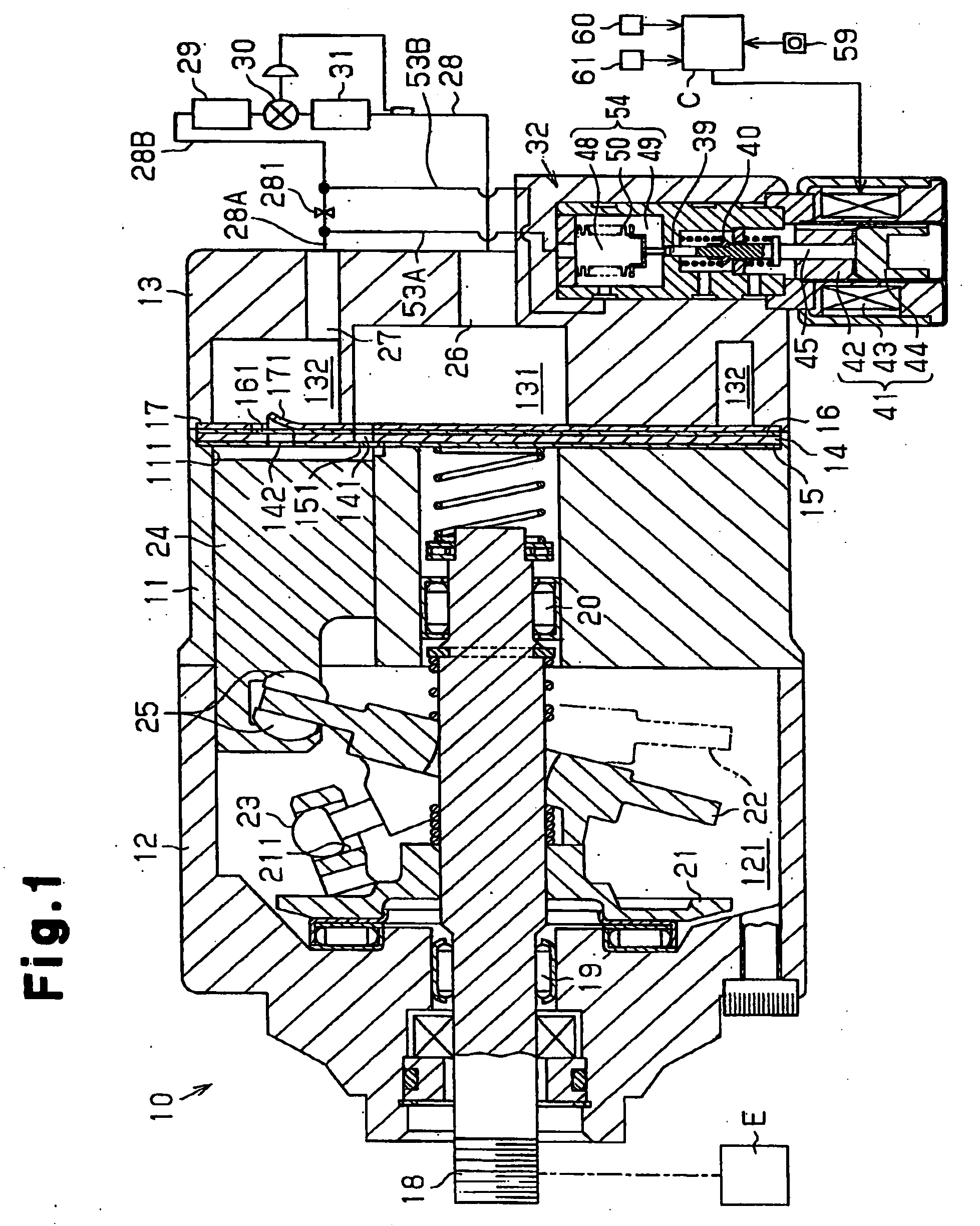
[0062] As shown in FIG. 1, a front housing member 12 is secured to the front end of a cylinder block 11. A rear housing member 13 is secured to the rear end of the cylinder block 11 with a valve plate 14, valve flap plates 15, 16, and a retainer plate 17 arranged in between. The cylinder block 11, the front housing member 12, and the rear housing member 13 form a housing of the compressor 10.

[0063] The front housing member 12 and the cylinder block 11 define a control pressure chamber 121. The front housing member 12 and the cylinder block 11 rotatably support a rotary shaft 18 with radial bearings 19, 20. The rotary shaft 18 projects from the control pressure chamber 121 to the outside, and receives power from a vehicle engine E, which is an external power source, through an electromagnetic clutch (not shown).

[0064] A rotary support 21 is fixed to the rotary shaft 18, and a swash plate 22 is supp...

fifth embodiment

[0267] In addition to the same advantages as the fifth embodiment, the sixteenth embodiment provides the following advantages.

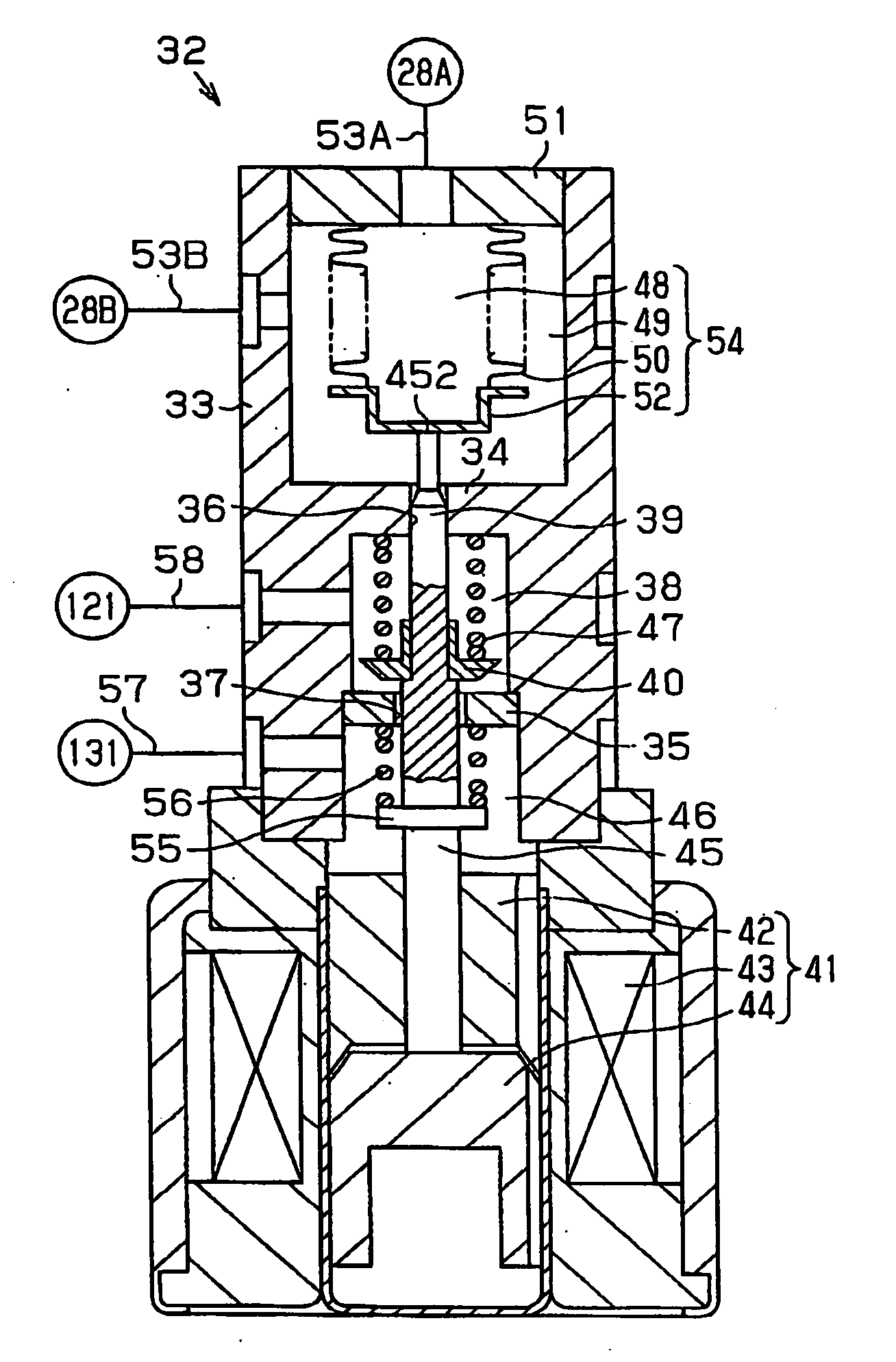
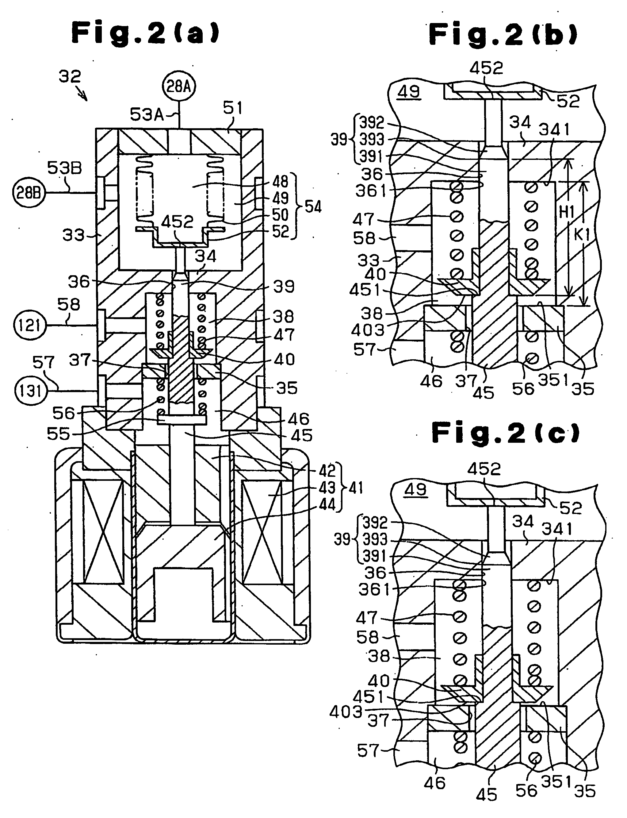
[0268] (16-1) In the displacement control valve 32C, the pressure in the discharge pressure introducing chamber 103 and the pressure in the suction pressure introducing chamber oppose each other with the transmission rod 45, which functions as a reciprocating body, in between. The displacement control valve 32C thus configured only controls the pressure difference between the discharge pressure and the suction pressure. That is, the displacement control valve 32C is controlled such that the difference between the discharge pressure and the suction pressure is balanced with the electromagnetic force of the solenoid 41. Since the displacement control valve 32C does not use the pressure sensing member 54 having the bellows 50 as in the first embodiment, the displacement control valve 32C of the present embodiment has a simpler construction than the displacement ...

third embodiment

[0286] An eighteenth embodiment will now be described with reference to FIGS. 30(a), 30(b), and 30(c). Like or the same reference numerals are given to those components that are like or the same as the corresponding components of the third embodiment shown in FIGS. 5(a) to 6(c) and the sixteenth embodiment shown in FIGS. 27 and 28.

[0287] A recess 671 is formed in a first valve body 67B, and an auxiliary rod 72 is inserted into the recess 671. An end face 723 of the auxiliary rod 72 selectively contacts a bottom 672 of the recess 671.

[0288] In the state of FIG. 30(a), the end face 723 of the auxiliary rod 72 is separated from the bottom 672. The first valve body 67B contacts the seating face 691 of the valve seat 69 so that the first valve hole 36 is closed. Since the first valve hole 36 is closed, refrigerant in the discharge pressure introducing chamber 103 does not flow into the shared chamber 38 through the first valve hole 36. Also, refrigerant in the discharge pressure introdu...


PUM


Abstract

A displacement control valve for a variable displacement compressor includes a first valve hole forming a part of a supply passage and a second valve hole forming a part of a discharge passage. Displacement of a reciprocating body is transmitted to each of first and second valve bodies so that each valve body opens or closes the corresponding valve hole. When the reciprocating body is within a predetermined displacement range, a double closing state occurs, in which the first valve body closes the first valve hole and the second valve hole closes the second valve hole. When the reciprocating body is out of the displacement range, a single closing state occurs. Therefore, the control valve prevents the first valve hole from opening concurrently with the second valve hole.

Description

BACKGROUND OF THE INVENTION [0001] The present invention relates to a displacement control valve employed for a variable displacement compressor, which valve supplies refrigerant from a discharge pressure zone to a control pressure chamber and discharges refrigerant from the control pressure chamber to a suction pressure zone, thereby controlling the pressure in the control pressure chamber, and changing the displacement of the compressor, accordingly. [0002] In a variable displacement compressor having a control pressure chamber for accommodating a tiltable swash plate, the inclination angle of the swash plate is reduced as the pressure in the control pressure chamber is increased, and increased as the control chamber pressure is reduced. When the inclination angle of the swash plate is reduced, the stroke of pistons is reduced, which decreases the displacement. When the inclination angle of the swash plate is increased, the piston stroke is increased, which increases the displacem...

Claims


Application Information

Patent Timeline
IPC IPC(8): F04B27/18
CPCF04B27/1804F04B2027/1813F04B2027/1854F04B2027/1831F04B2027/1827
Inventor UMEMURA, SATOSHIKAWAGUCHI, MASAHIROOTA, MASAKIHIROSE, TATSUYAHASHIMOTO, YUJIFUKANUMA, TETSUHIKO
Owner TOYOTA IND CORP
Why Eureka
Try Eureka