Variable speed flat transmission and variable diameter pulley for use in same

a variable speed belt and flat transmission technology, applied in the direction of gearing, gearing elements, hoisting equipment, etc., can solve the problems of low precision incremental adjustment and relative complexity of variable speed belt transmissions, and achieve the effect of greater variance in the diameter of the belt support surfa

Inactive Publication Date: 2005-12-29
VARGAS ELADIO A
View PDF18 Cites 39 Cited by
  • Summary
  • Abstract
  • Description
  • Claims
  • Application Information

AI Technical Summary

Benefits of technology

[0004] In accordance with a presently preferred embodiment of the present invention, a belt drive system is provided that employs a variable diameter drive pulley and a variable diameter driven pulley interconnected by a flat belt and operative to vary the rotational speed of the driven pulley as in a variable speed transmission. Each pulley includes an internal fluid pressure chamber and diametrically aligned pairs of radially movable pistons or lift bars that support transverse lift rods at their outer ends such that the lift rods lie on a common but variable diameter coaxial with the rotational axis of the pulley. Axially spaced circular guide plates are fixed coaxially with and transversely to the rotational axis of each pulley and form end boundaries for the fluid pressure chambers. The guide plates have radial through-slots that receive the opposite ends of the lift rods and cooperate with juxtaposed pairs of coaxial guide discs that are supported for rotation relative to the corresponding guide plates and relative to each other in opposite directions. The gui

Problems solved by technology

A significant drawback in the known variable diameter pulleys employed in variable speed transmissions or belt drive systems is tha

Method used


Image

  • Variable speed flat transmission and variable diameter pulley for use in same
  • Variable speed flat transmission and variable diameter pulley for use in same
  • Variable speed flat transmission and variable diameter pulley for use in same

Examples


Embodiment Construction

[0015] The present invention is susceptible of various forms. Accordingly, there is shown in the drawings, and will hereinafter be described, preferred exemplary but non-limiting embodiments of the invention with the understanding that the described embodiments are not intended to limit the invention to the specific embodiments disclosed.

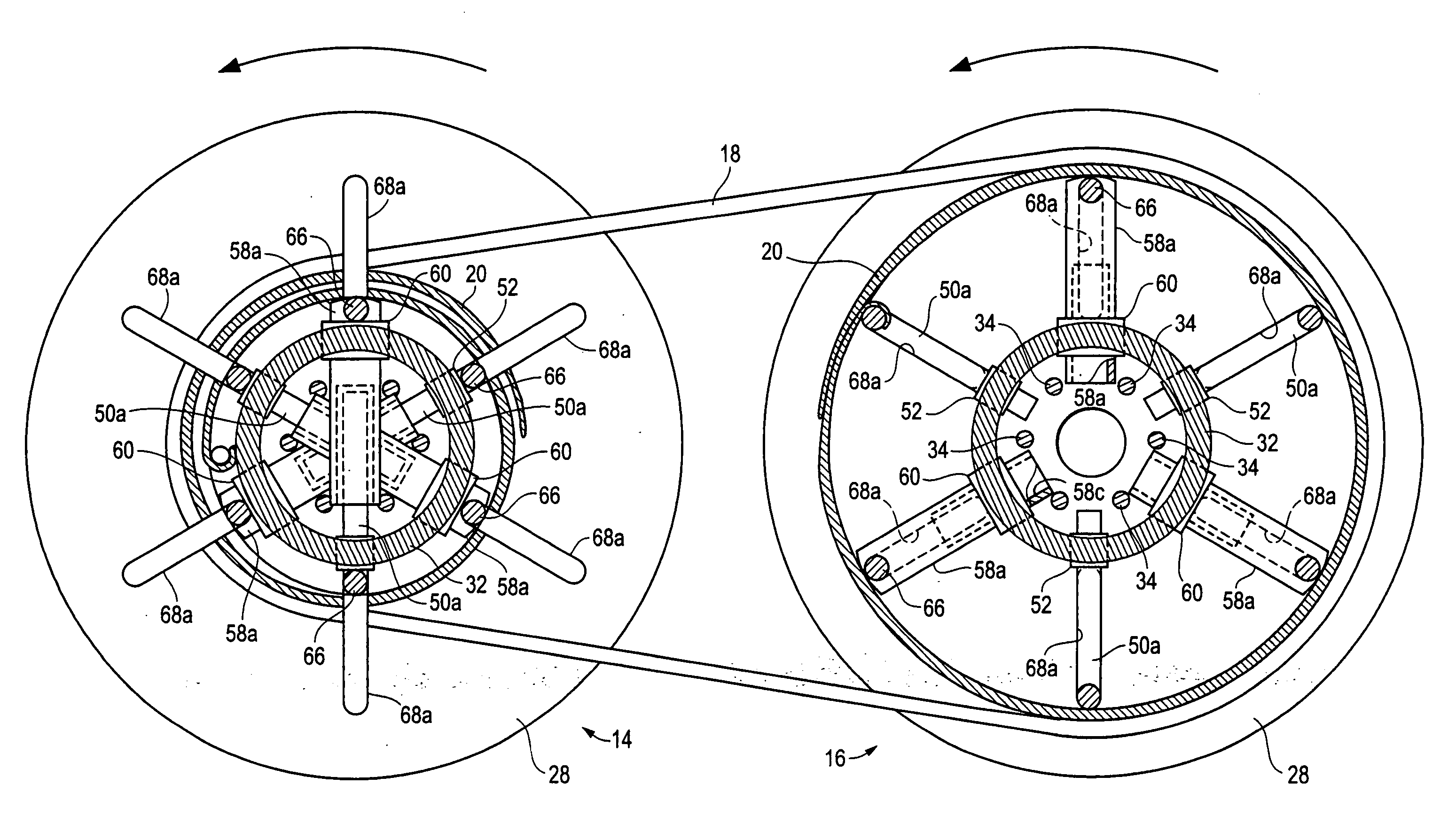
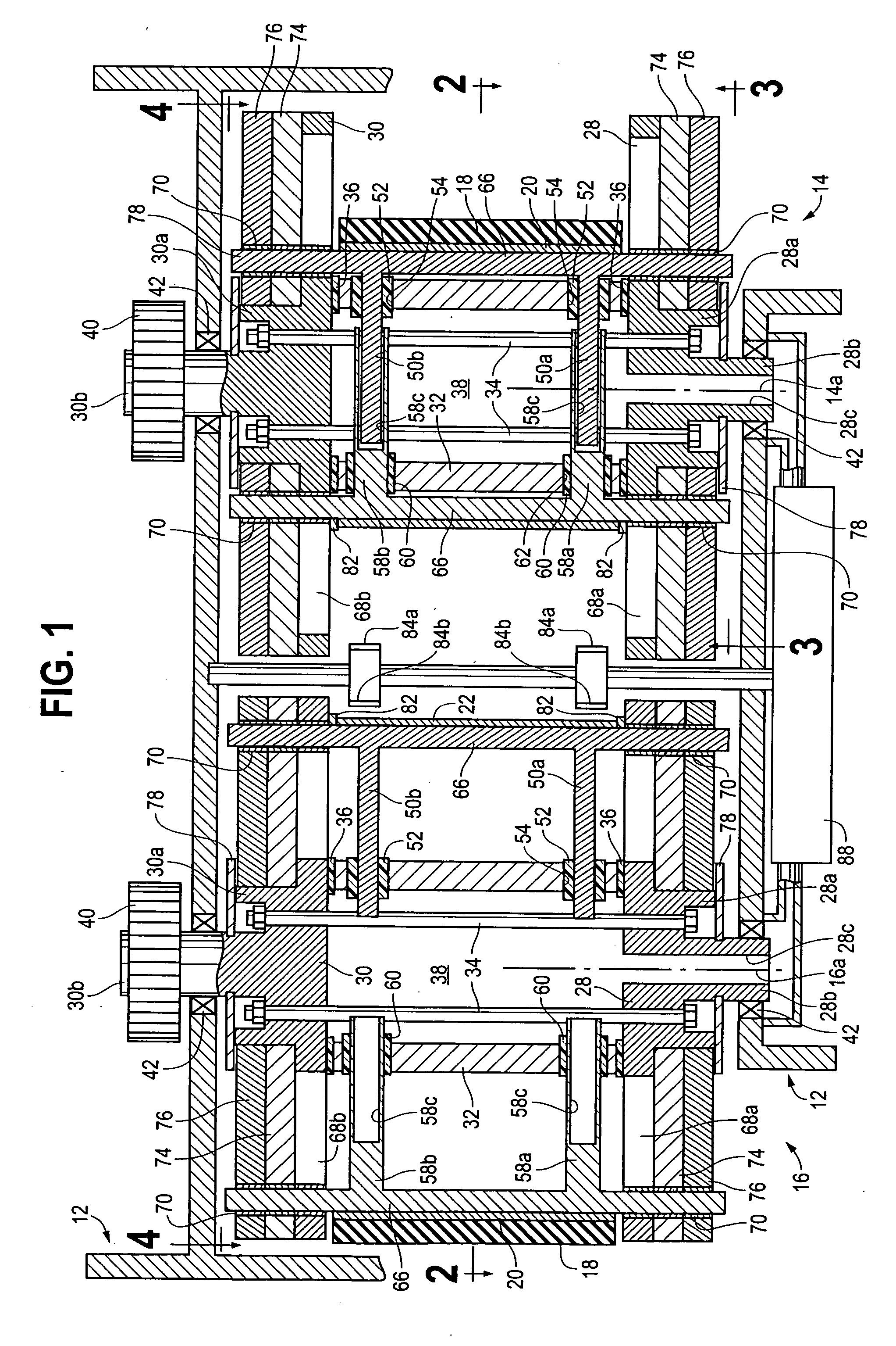
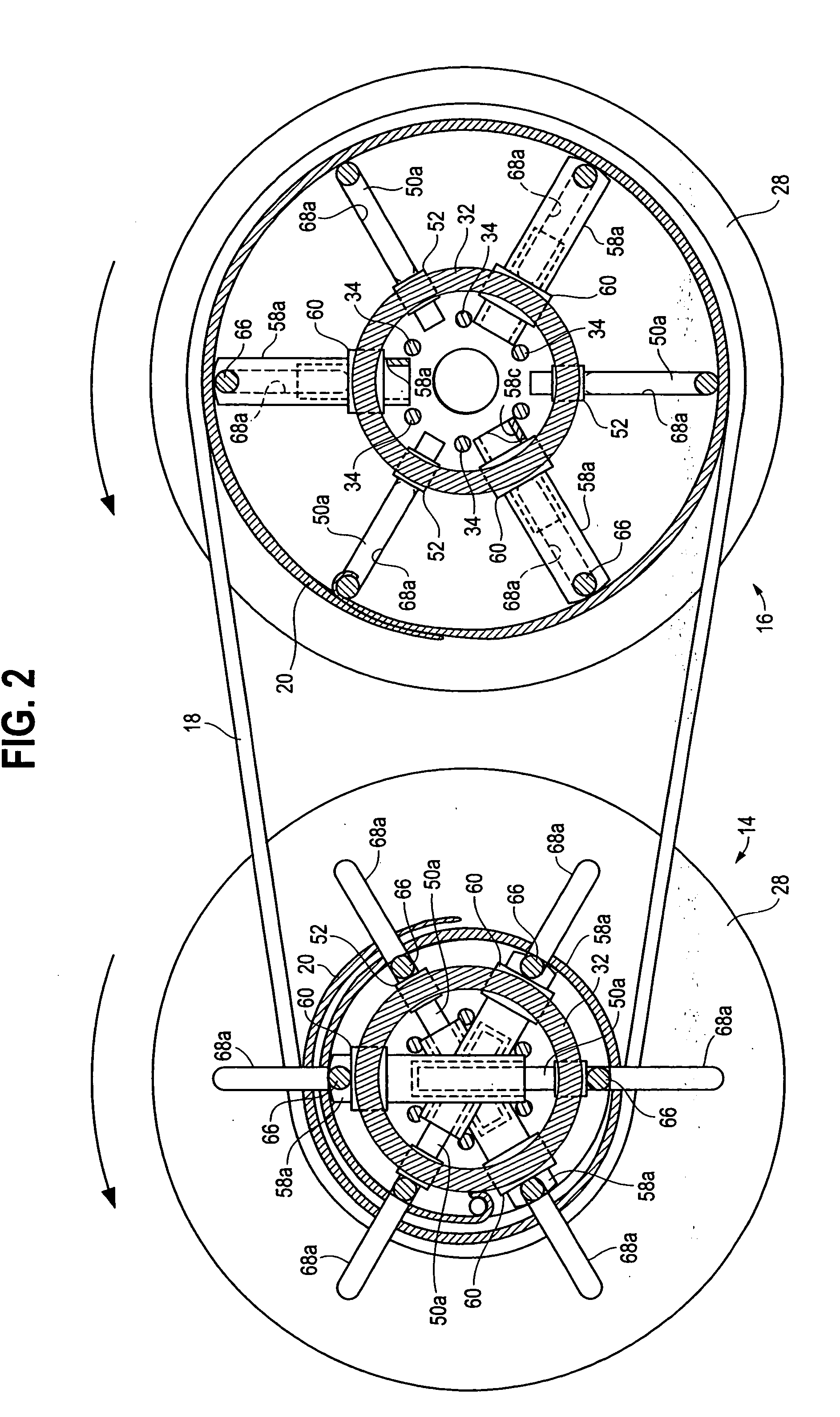
[0016] Referring now to the drawings, and in particular to FIG. 1, a variable speed flat belt transmission constructed in accordance with a preferred embodiment of the invention is indicated generally at 10. Very generally, the variable speed flat belt transmission 10, which may alternatively be referred to as a variable speed transmission or a belt drive system, includes a housing 12 adapted to receive and support a variable diameter drive pulley 14 and a variable diameter driven pulley 16. The drive pulley 14 and driven pulley 16 are substantially identical and are supported by the housing 12 so as to define parallel coplanar longitudinal rotatio...


PUM


Abstract

A belt drive system employs variable diameter drive and driven pulleys interconnected by a flat belt and operative to vary the rotational speed of the driven pulley as in a variable speed transmission. Each pulley includes an internal fluid pressure chamber and diametrically aligned pairs of radially movable pistons or lift bars that support transverse lift rods at their outer ends. Axially spaced circular guide plates form end boundaries for the fluid pressure chamber and have radial through-slots that cooperate with arcuate slots in juxtaposed pairs of coaxial guide discs to receive opposite ends of the lift rods and effect synchronous radial movement of the lift rods in response to pressure changes within the fluid pressure chamber. An elongated flexible spring-like support member is attached at one end to a lift rod and extends in supported relation circumferentially over and about the lift rods to define a variable diameter belt support surface. The diametrically aligned pistons are adapted for telescoping relation during radial inward movement of the lift rods, thereby enabling greater variance in the diameter of the belt support surface for a given size pulley. Electronic sensors sense the rotational position of each pulley during rotation and cooperate with a source of fluid pressure to maintain the desired pulley diameter and belt tension.

Description

FIELD OF THE INVENTION [0001] The present invention relates generally to variable diameter pulleys that find particular application in variable speed flat belt transmissions, and more particularly to a variable diameter pulley that employs an improved arrangement of fluid pressure actuated lift rods, guide plates and guide discs that effect simultaneous equal radial movement of the lift rods relative to the rotational axis of the pulley during changes in the diameter of an annular belt support surface supported by the lift rods. BACKGROUND OF THE INVENTION [0002] Variable speed transmissions are known that utilize variable diameter pulleys interconnected by a flat belt so as to create a drive pulley and a driven pulley. See, for example, U.S. Pat. Nos. 4,024,772, 4,295,836 and 4,714,452. The variable diameter pulleys utilized in known variable speed mechanisms or transmissions employ parallel belt support members disposed on a common diameter coaxial with the rotational axis of the ...

Claims


Application Information

Patent Timeline
IPC IPC(8): F16H9/02F16H9/10F16H55/30F16H55/36F16H55/54
CPCF16H55/54F16H9/10
Inventor VARGAS, ELADIO A.
Owner VARGAS ELADIO A
Why Eureka
Try Eureka