Multi-beam radar sensor

a radar sensor and beam technology, applied in the direction of instruments, measurement devices, antennas, etc., to achieve the effects of reducing precision, reducing variance, and improving accuracy in azimuth angle determination

Active Publication Date: 2011-06-14
ROBERT BOSCH GMBH
View PDF51 Cites 8 Cited by
  • Summary
  • Abstract
  • Description
  • Claims
  • Application Information

AI Technical Summary

Benefits of technology

[0008]It is an object of the present invention to provide a multi-beam radar sensor having improved angular detection capabilities.
[0010]In particular, the preliminary focusing lens has the effect that a portion of the beams emitted by the four antenna elements is focused before striking the main lens. This brings about a change in the aperture occupancy behind the lens such that a broader principal maximum occurs in the azimuth diagram, so that the precision of the determination of the azimuth angle is improved. In a conventional radar sensor of the same design but without preliminary focusing lens, the principal maximum in the azimuth diagram has a width of only approximately 20° (zero positions at ±10°), so that greater variance and thus reduced precision results in the angle estimation at azimuth angles in the vicinity of ±10°. On the other hand, in the radar sensor according to the present invention the first zero positions are shifted outwardly to a considerable extent, i.e., to higher angles, thereby allowing the determination of the azimuth angle with a significantly lower variance.
[0011]The preliminary focusing lens may advantageously be disposed directly on the inner surface of the collective lens, e.g., a plano-convex lens. This allows a simple and cost-effective production.

Problems solved by technology

The transmission characteristic of such a multi-beam radar sensor is a function of the geometry of the individual antenna elements and the optical characteristics of the collective lens, but is also affected by interference effects between the signals emitted by the different antenna elements.

Method used


Image

  • Multi-beam radar sensor
  • Multi-beam radar sensor
  • Multi-beam radar sensor

Examples


Embodiment Construction

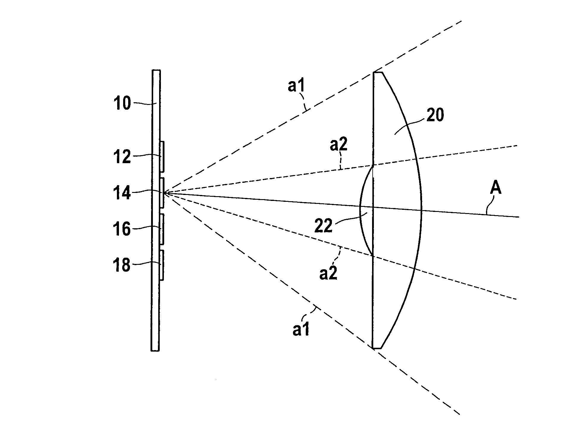
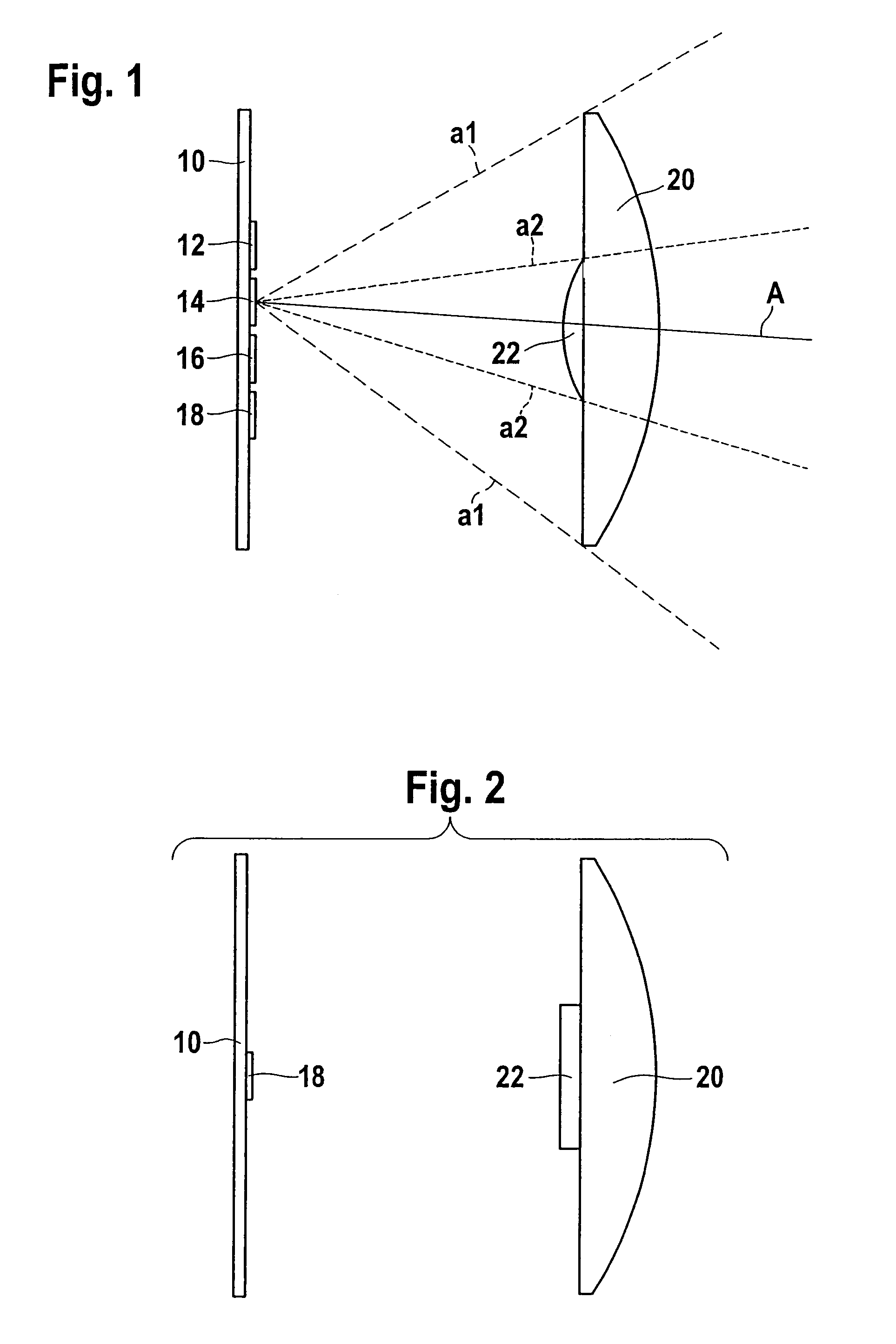
[0018]The radar sensor shown in FIG. 1 has four antenna elements (patches) 12, 14, 16, 18 mounted on a shared mounting plate 10. Spaced at a distance to mounting plate 10 is a collective lens 20 such as an aplanatic plano-convex lens whose planar side faces mounting place 10, collective lens 20 having a refractive effect for radar radiation. The radiation emitted by all four antenna elements passes through collective lens 20 and is focused by it.

[0019]In the radar sensor examined in this instance by way of example, a monostatic antenna principle is realized, i.e., each antenna element 12 acts both as transmit antenna and as receiving antenna. As a consequence, the radiation reflected by a radar sensor, which radiation was emitted by a specific antenna element, is also refocused by collective lens 20 in the direction of the particular antenna element, where it is received.

[0020]Since antenna elements 12, 14, 16, 18 are uniformly offset with respect to each other in the horizontal dir...


PUM


Abstract

A multi-beam radar sensor has a plurality of antenna elements disposed next to each other, a collective lens situated at a distance in front of the antenna elements, and an additional preliminary focusing lens disposed in such a way that it affects only a portion of the radar radiation transmitted from, and / or received by, the antenna elements.

Description

BACKGROUND OF THE INVENTION[0001]1. Field of the Invention[0002]The present invention relates to a multi-beam radar sensor having a plurality of antenna elements situated next to each other, a collective lens disposed with distance in front of the antenna element, and an additional preliminary focusing lens, and the present invention also relates to a radar sensor having angular resolution for use in motor vehicles.[0003]2. Description of Related Art[0004]The radar radiation emitted or received by the plurality of antenna elements disposed next to each other passes through the collective lens shared by all antenna elements and is bundled in this manner. However, because of the offset of the individual antenna elements in the lateral direction, the radar beams generated and / or received thereby are likewise angularly offset with respect to each other. If a reflective radar object is hit by multiple beams, then it is possible to determine, or at least estimate, the azimuth angle of the...

Claims


Application Information

Patent Timeline
Patent Type & Authority Patents(United States)
IPC IPC(8): G01S7/02G01S13/93G01S7/00G01S13/00G01S13/931
CPCG01S13/424H01Q3/2658H01Q25/002H01Q25/00H01Q19/062G01S13/931
Inventor BINZER, THOMAS
Owner ROBERT BOSCH GMBH
Why Eureka
Try Eureka