
Miter saw having digital display capable of displaying specific angle

Active Publication Date: 2006-01-05
HITACHI KOKI CO LTD
View PDF3 Cites 18 Cited by
  • Summary
  • Abstract
  • Description
  • Claims
  • Application Information

AI Technical Summary

Benefits of technology

[0009] It is therefore an object of the present invention to provide a miter saw capable of displaying specific rotation angle(s) and / or specific tilting angle(s) when the turntable and the circular saw blade is moved to the positions corresponding to the specific rotation angle and the specific tilting angle or to angles close to the specific rotation angle and the specific tilting angle.

Problems solved by technology

However, display of the angles at an integral multiple of the unit rate only may cause another disadvantage.

Method used


Image

  • Miter saw having digital display capable of displaying specific angle
  • Miter saw having digital display capable of displaying specific angle
  • Miter saw having digital display capable of displaying specific angle

Examples


first embodiment

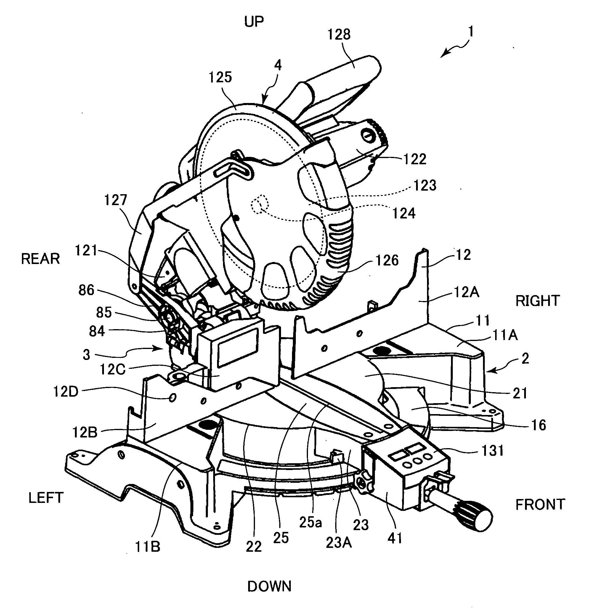
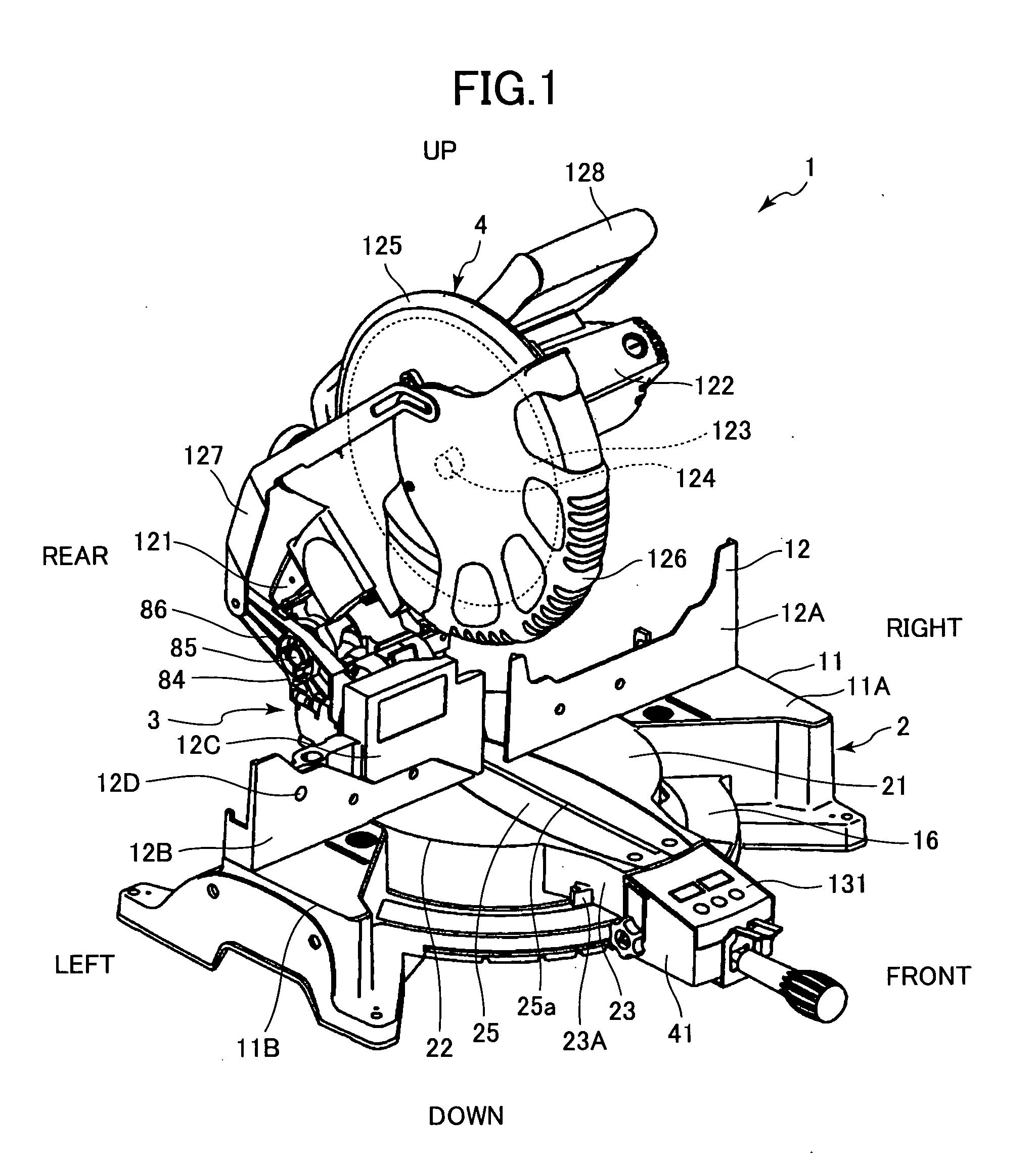
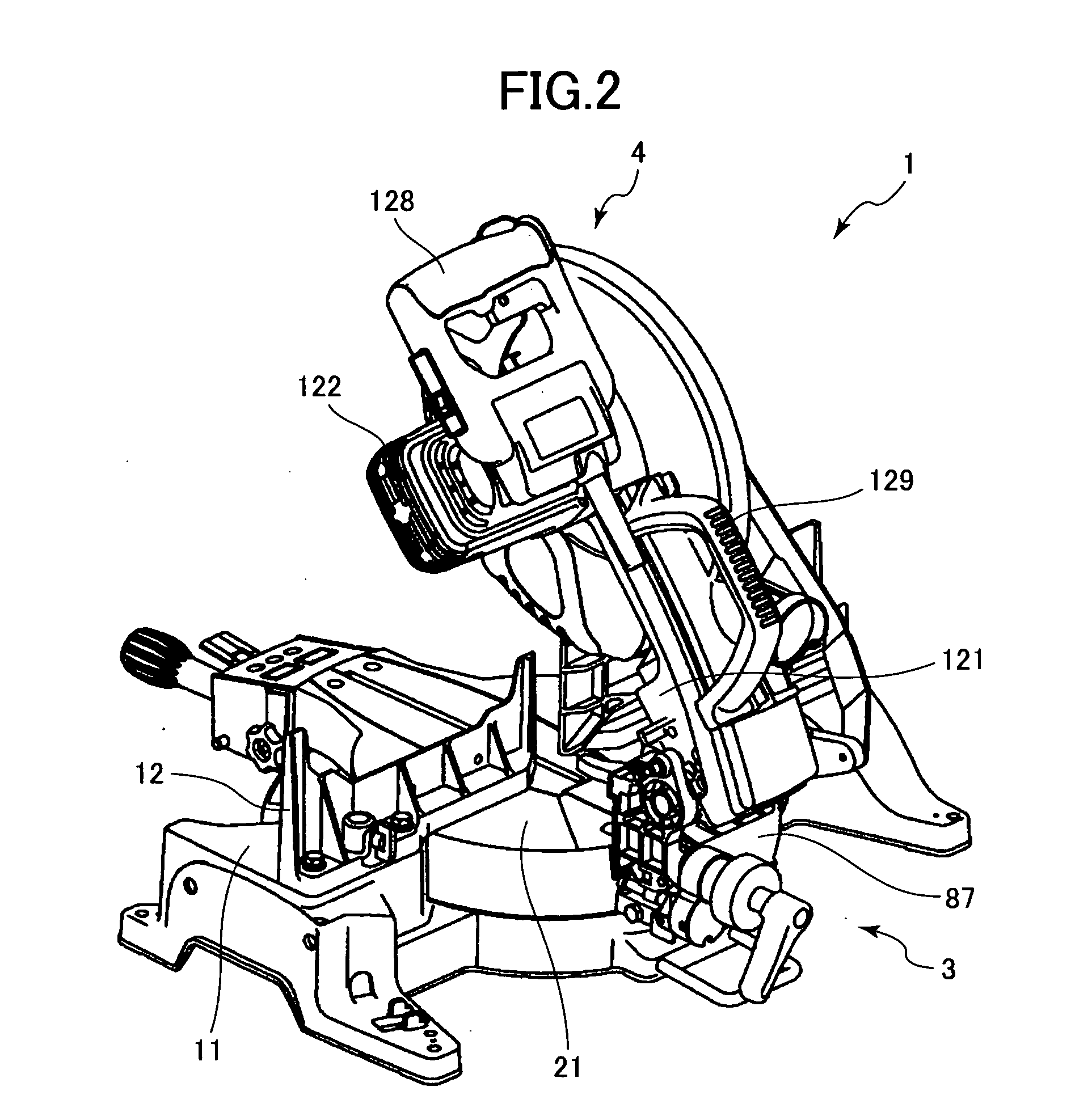
[0062] A miter saw according to the present invention will be described with reference to FIGS. 1 through 31, 47 and 48. As shown in FIG. 1, the miter saw 1 includes a base section 2 installed on a stand or a floor for mounting thereon a workpiece such as a wood, a circular-saw unit 4 that cuts a workpiece, and a support section 3 supporting the circular saw unit 4 pivotally movably toward and away from the base section 2 and laterally tiltably relative to the base section.

[0063] As shown in FIG. 1, the base section 2 includes a base 11 serving as a ground section, a turntable 21 and a fence 12. The turntable 21 is supported on the base 11 and is rotatable about its axis with respect to the base 11. The turntable 21 cooperates with the base 11 to support a workpiece such as a wood block. The fence 12 laterally extends over the base 11 and is supported on the base 11. The fence 12 has an abutment surface extending in the lateral direction and facing frontward in contact with a side s...

second embodiment

[0165] To this effect, in the miter saw EEPROM 143 stores therein a table. The table shows the relationship between each range of detected pulse numbers and each specific rotation angle. In this way, even if the specific rotation angle is not the integral multiple of the predetermined display unit rotation angle, the microcomputer 142 performs processing for displaying the specific rotation angle at the digital display 131 if the pulses detected from the rotation amount detection unit 51 is indicative of an angle within a predetermined rotation angle range containing the specific rotation angle, such as from 35.25 to 35.30 and from 35.30 to 35.35. Accordingly, the user can recognize that the turntable 21 has been rotated to the specific rotation angle whereupon a specific building material such as a molding member can be cut at the specific rotation angle of the turntable 21.

[0166] The miter saw according to the second embodiment also includes the tilting amount detection unit 101....


PUM

PropertyMeasurementUnit
Angleaaaaaaaaaa

Abstract

A miter saw capable of displaying a specific rotation angle of a turntable and a specific tilting angle of a circular saw blade when the turntable is moved to a position within a predetermined specific rotation angle range and when the circular saw blade is moved to a position within a predetermined specific tilting angle range, respectively. Normally, a digital display displays the rotation angle at a rate of a predetermined display unit rotation angle which is an integral multiple of a predetermined unit rotation angle corresponding to a single pulse. However, if the turntable is moved to the position within the predetermined specific rotation angle range, the specific rotation angle which is not the integral multiple of the predetermined display unit rotation angle is displayed at the digital display. The same is true with respect to the tilting angle.

Description

BACKGROUND OF THE INVENTION [0001] The present invention relates to a miter saw, and more particularly, to such a miter saw having an angularly rotatable turntable, and a circular saw unit laterally tiltable relative to the turntable. [0002] Japanese Patent Application Publication No. 2000-254817 discloses a miter saw including a base section, a support section, and a circular saw unit. The base section includes a base and a turntable mounted on the base and rotatable about its axis. A workpiece is mounted on the turntable. The support section upwardly extends from the turntable and laterally tiltable. The circular saw unit is positioned above the base section and is pivotally movably supported to the support section. The circular saw unit includes a circular saw blade and a motor for rotating the blade. [0003] For angled cutting, the turntable is angularly rotated about its axis to change the angle of the side surface of the circular saw blade relative to a fence. For slant cutting...

Claims


Application Information

Patent Timeline
IPC IPC(8): B26D1/14
CPCB23D45/044B23D59/002B23D45/048Y10T83/7697Y10T83/7705Y10T83/7788Y10T83/8773
Inventor TERASHIMA, HIDEAKIKAWANO, YOSHIKAZUTAKANO, NOBUHIRO
Owner HITACHI KOKI CO LTD
Learn More