Vehicle adapted to move along a rail

Active Publication Date: 2006-01-05
ALSTOM TRANSPORT TECH SAS
View PDF2 Cites 22 Cited by
  • Summary
  • Abstract
  • Description
  • Claims
  • Application Information

AI Technical Summary

Benefits of technology

[0008] An object of the present invention is to propose a vehicle of the type cited a

Problems solved by technology

However, the body is rigid and is not able to follow the curvature of the rail.
However, such systems are complicated, because the unders

Method used


Image

  • Vehicle adapted to move along a rail
  • Vehicle adapted to move along a rail
  • Vehicle adapted to move along a rail

Examples


Embodiment Construction

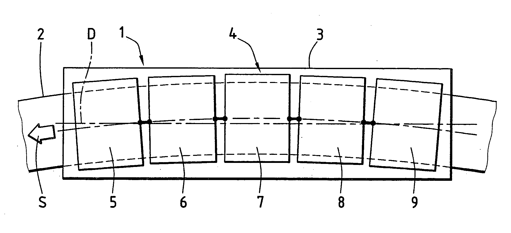
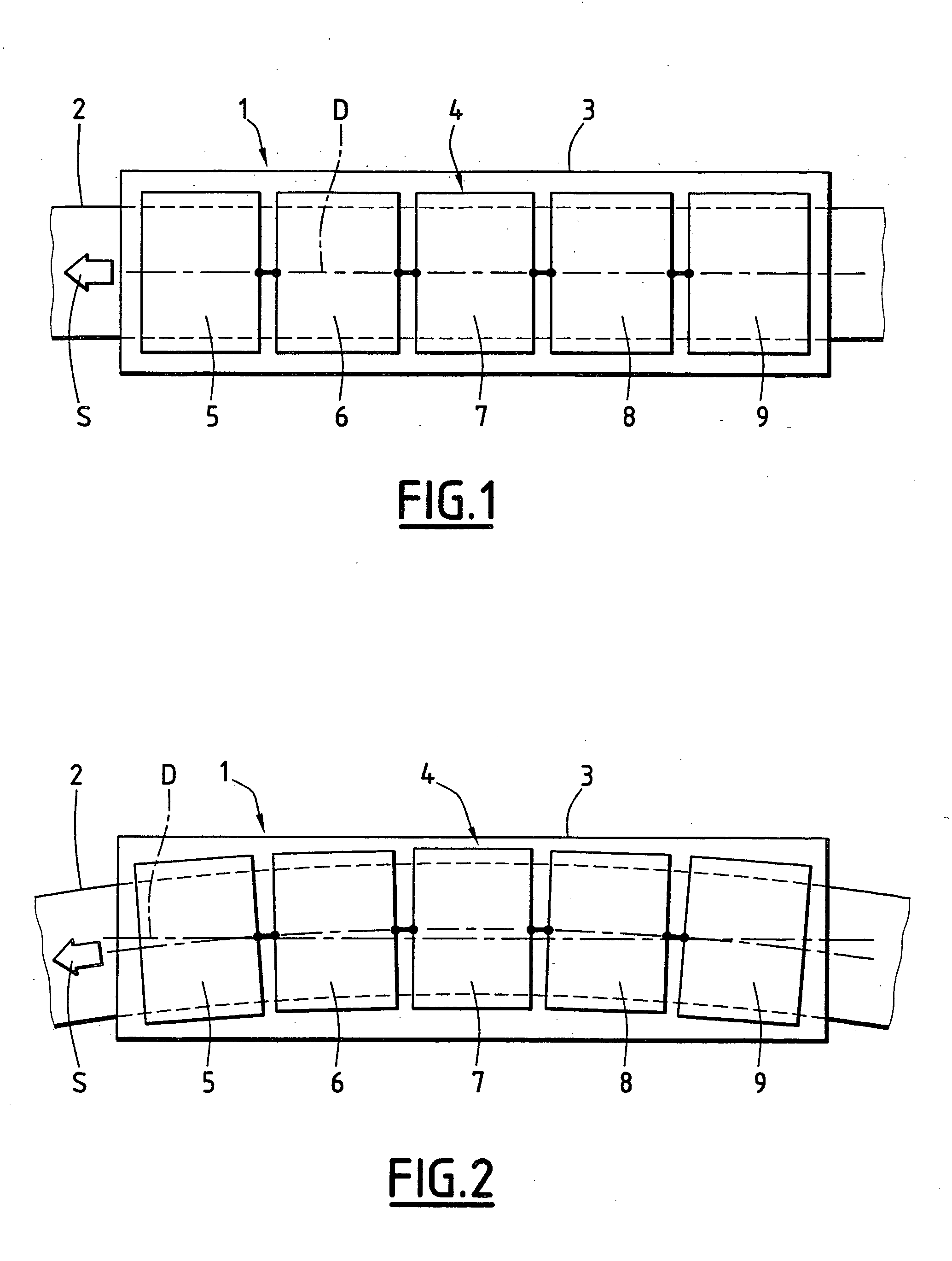
[0028]FIG. 1 shows a vehicle 1 adapted to move along a rail 2 and comprising a body 3 resting on the rail 2 via a levitation system 4 integrated into the vehicle.

[0029] Throughout the description below, the orientations referred to are the usual orientations of a rail vehicle. Accordingly, the terms “front”, “rear”, “right”, “left”, “lateral”, “longitudinal”, “upper” and “lower” are to be understood with respect to a longitudinal axis of the vehicle indicated by a chain-dotted line D and to the direction of movement of the vehicle, indicated by an arrow S in FIG. 1.

[0030] The levitation system 4 comprises a plurality of modules arranged in a line along the longitudinal axis D under the body 3, here five modules 5, 6, 7, 8, 9. The levitation system 4 comprises, from the front towards the rear, a first or front module 5, a second module 6, a third module 7, a fourth module 8, and a fifth or rear module 9. The body 3 bears on each of the modules 5, 6, 7, 8, 9 in a main bearing direct...


PUM


Abstract

This vehicle comprises a body and a levitation device, the body bearing in operation on the levitation device which comprises a first levitation module and a second levitation module connected to the body, and capable of moving to allow the modules to turn relative to the body. The vehicle comprises means for synchronizing movement of the levitation modules comprising a first hydraulic ram between the first module and the body, a second hydraulic ram between the second module and the body, and a fluid-flow circuit connecting the first and second rams to synchronize the actions of the rams. Application to magnetic levitation rail vehicles, for example.

Description

[0001] The present invention relates to a vehicle adapted to move along a rail and comprising a body and a device for levitating the body on the rail, wherein the body bears in operation on the levitation device in a main bearing direction and the levitation device comprises: [0002] a first levitation module and a second levitation module connected to the body and capable of moving in a bearing plane perpendicular to the main bearing direction to allow the modules to turn relative to the body, in particular when the vehicle is moving along a curved section of the rail; and [0003] means for synchronizing movement of the first and second levitation modules relative to the body in the bearing plane. BACKGROUND OF THE INVENTION [0004] In certain vehicles equipped with magnetic levitation modules, modules are situated in line on the rail. The body, which is rigid, bears substantially vertically on a plurality of modules. The modules are guided on the rail. On rectilinear sections of the ...

Claims


Application Information

Patent Timeline
IPC IPC(8): B60L13/04B60L13/10B61F5/44
CPCB60L13/10B60L2200/26B61F5/44B60L13/04
Inventor NAST, JEAN-DANIEL
Owner ALSTOM TRANSPORT TECH SAS
Why Eureka
Try Eureka