Mobile road or floor saw

a road or floor saw, self-propelled technology, applied in the direction of metal sawing devices, metal sawing apparatus, manufacturing tools, etc., can solve the problems of -driven transmissions not providing a “, modern saw blades are not being driven, and lack of flexibility in other directions

Inactive Publication Date: 2006-01-05
DIAMOND PROD
View PDF19 Cites 21 Cited by
  • Summary
  • Abstract
  • Description
  • Claims
  • Application Information

AI Technical Summary

Benefits of technology

[0007] The present invention provides an improvement over the prior art by providing a floor or road saw that includes a multi-speed transmission that includes a neutral position. The transmission of the present invention does not require the use of belts, polychains or clutches that require regular maintenance and / or replacement. Moreover, the transmission of the saw may be shifted when the transmission is engaged and shifted through a set of gears in a sequential manner. Further, the transmission is well suited for use on saws where power source or prime mover is disposed parallel to the longitudinal axis of the saw.

Problems solved by technology

Even with such an improvement, modern saws lack flexibility in other areas.
These belt-driven transmissions do not provide a “neutral” configuration where the transmission is engaged, but the saw blade is not being driven except by means of a conventional clutch that is subject to wear.
Often these transmissions operate at only a single speed, and if a multiple speed transmission is provided, it does not afford sequential shifting which avoids over-speeding a blade by accidentally shifting to a very high gear.
Also, the prior art transmissions do not provide the convenience of being able to shift gears during the cutting operation (i.e., “on the fly”).

Method used


Image

  • Mobile road or floor saw
  • Mobile road or floor saw
  • Mobile road or floor saw

Examples


Embodiment Construction

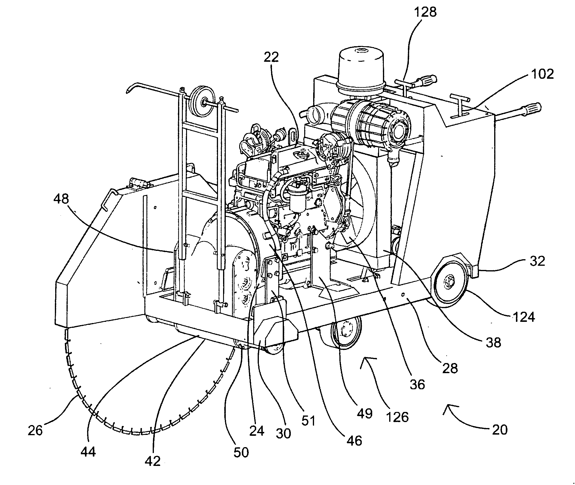
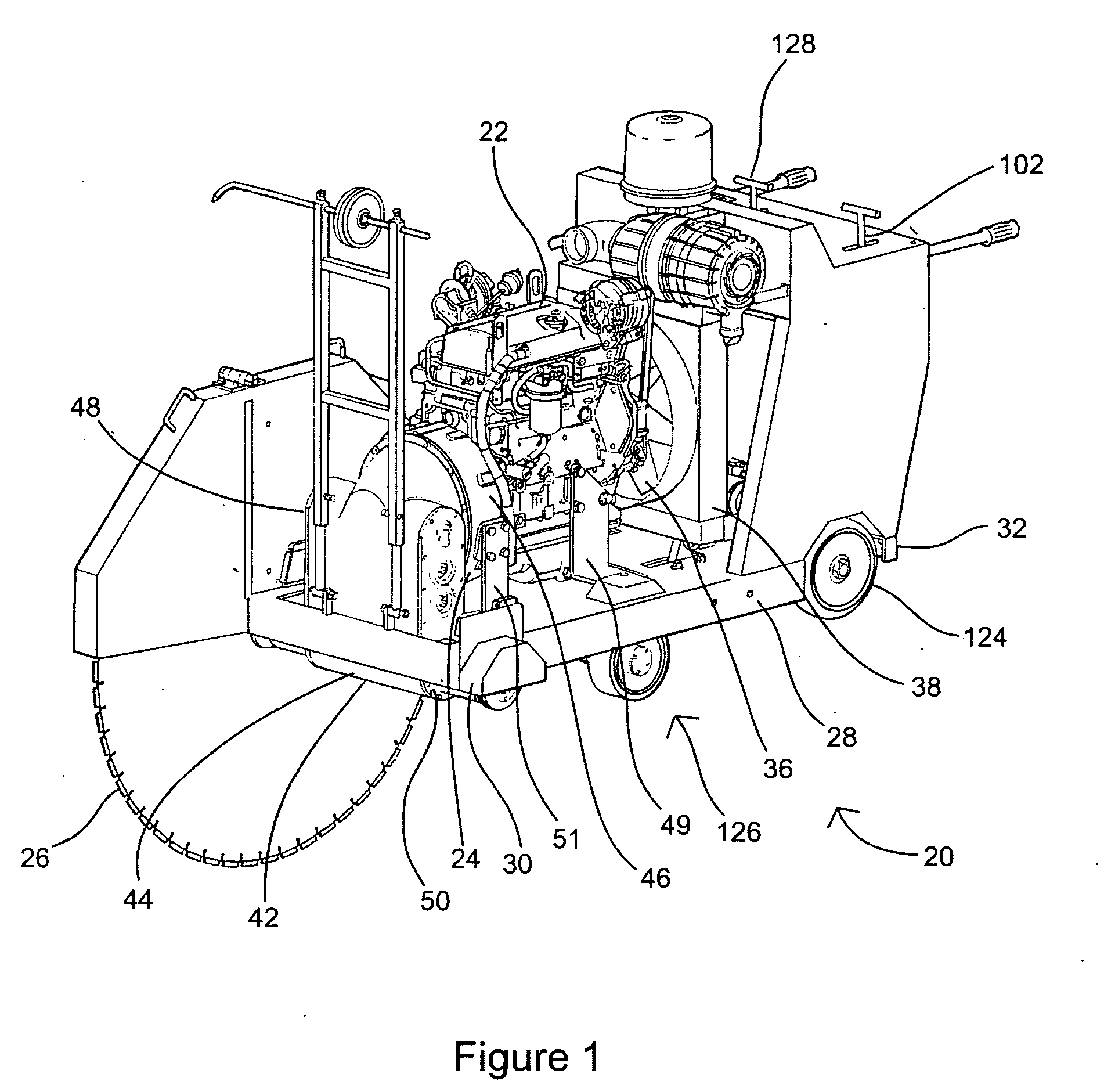
[0024] Referring to the drawings, a mobile road or floor saw 20 according to the present invention is illustrated. The saw 20 includes an engine 22 that is used to drive a transmission 24 that in turn drives a saw blade 26. The saw 20 is used to cut seams, notches and / or grooves into or through asphalt, concrete, stone or other similar surfaces.

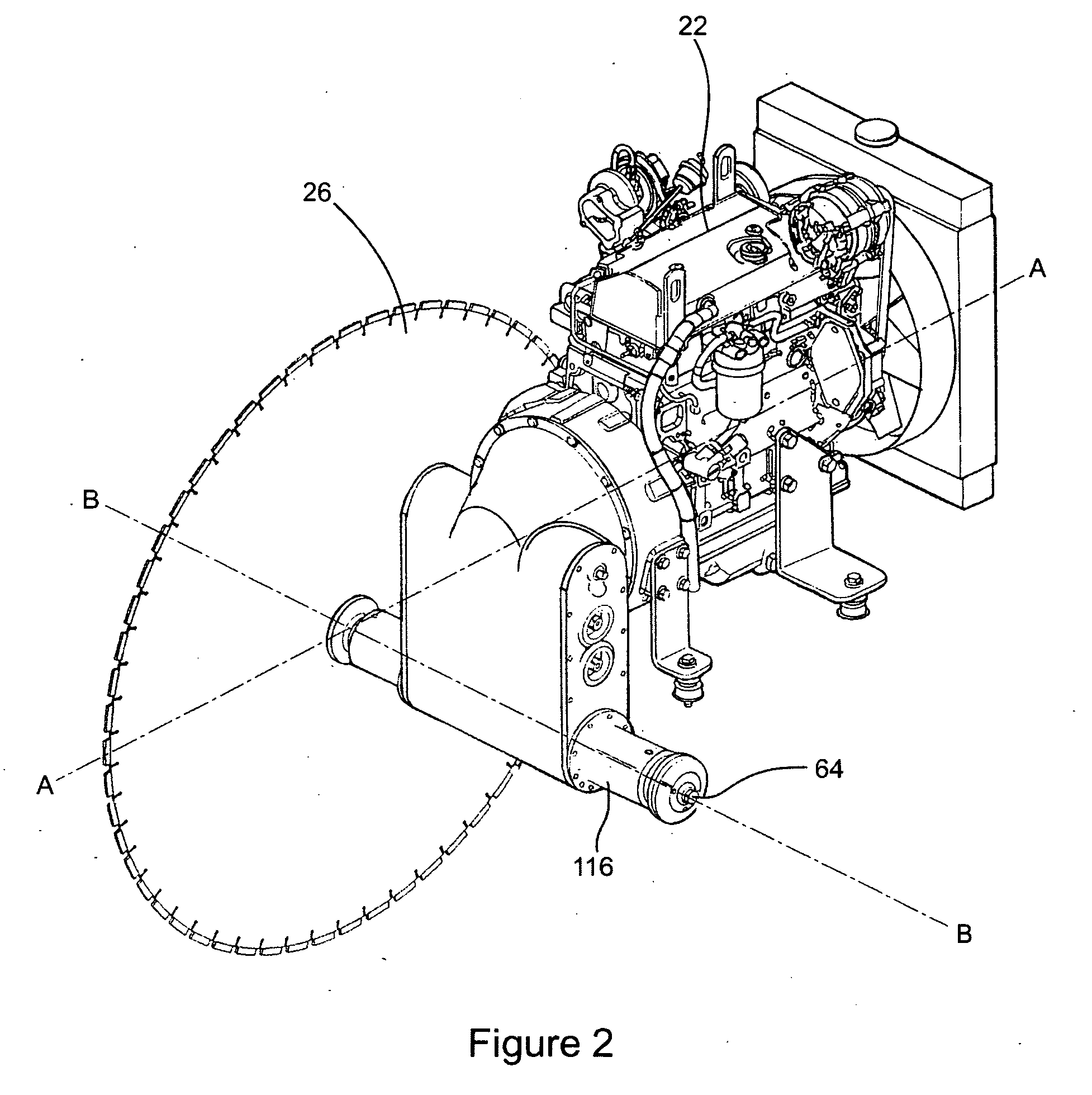
[0025] Referring to FIGS. 1-3, the engine or prime mover 22 of the saw 20 has a generally rectangular shape and is supported upon a generally rectangular frame 28. The frame 28 has a front end 30 and a rear end 32. The engine 22 is of a type generally known in the art and is oriented with a driven output shaft 34 parallel to an axis “A-A” defined by the length of the rectangular frame 28. The engine 22 includes means for cooling, such as a fan 36 and radiator 38, at an end opposite the output shaft 34 and adjacent to the rear end 32 of the frame 28. It will be appreciated that prime mover 22 may comprise a gasoline, diesel or propane (intern...


PUM

PropertyMeasurementUnit
rotationaaaaaaaaaa
longitudinal lengthaaaaaaaaaa
multi-speedaaaaaaaaaa

Abstract

A floor or road saw that includes a multi-speed transmission that includes a neutral position. The transmission does not require the use of belts, polychains or clutches that require regular maintenance and/or replacement. Moreover, the transmission of the saw may be shifted when the transmission is engaged and shifted through a set of gears in a sequential manner. Further, the transmission is well suited for use on saws where power source or prime mover is disposed parallel to the longitudinal axis of the saw.

Description

BACKGROUND OF THE INVENTION [0001] 1. Field of the Invention [0002] The present invention applies to road or floor saws and more specifically to self-propelled operator-guided or steerable saws supported on a frame with wheels. [0003] 2. Description of the Related Art [0004] In the concrete industry, when building bridges, buildings, roads and the like, it is often necessary to pour large horizontal slabs of concrete. Once poured, it is usually necessary to machine the slab. Such machining may include cutting seams completely through the slab (to form expansion joints and to allow for foundation shifting), cutting notches partially into the slab (to create stress cracks along which the slab will split), cutting multiple grooves into the slab to create a high friction surface such as for bridges, grinding the surface of the slab and the like. Concrete saws are also used in the demolition or removal of concrete, such as during the sawing and replacement of bridge decks. Various types ...

Claims


Application Information

Patent Timeline
Patent Type & Authority Applications(United States)
IPC IPC(8): B28D1/04
CPCB28D1/045B23D47/12
Inventor MARQUES, PETERMERTES, ANTHONY
Owner DIAMOND PROD
Why Eureka
Try Eureka