Energy generating mechanism

Inactive Publication Date: 2006-01-05
CHIU CHIH HO
View PDF2 Cites 12 Cited by
  • Summary
  • Abstract
  • Description
  • Claims
  • Application Information

AI Technical Summary

Benefits of technology

[0004] The present invention relates to an energy generating mechanism which comprises an energy producing device and an energy collection device. The energy producing device has a truss on which a first link and a second link are pivotably and perpendicularly connected thereon. Each of the first link and the second link has two boxes on two ends

Problems solved by technology

Human consumes energy in a mass scale and the remained energy source on earth reaches a critical point which substantially threatens the living of human beings

Method used


Image

  • Energy generating mechanism
  • Energy generating mechanism
  • Energy generating mechanism

Examples


Embodiment Construction

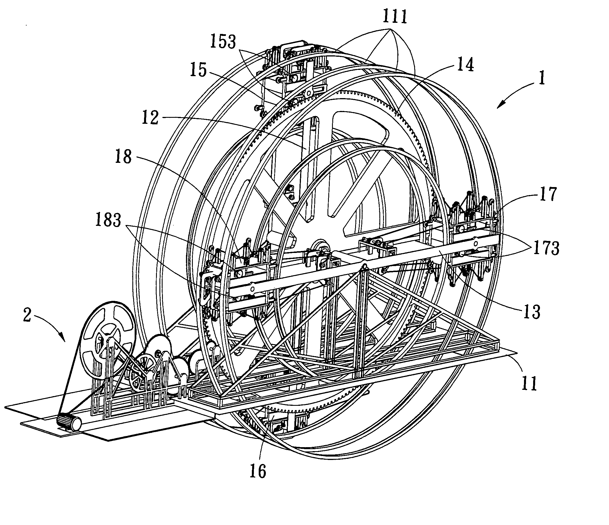
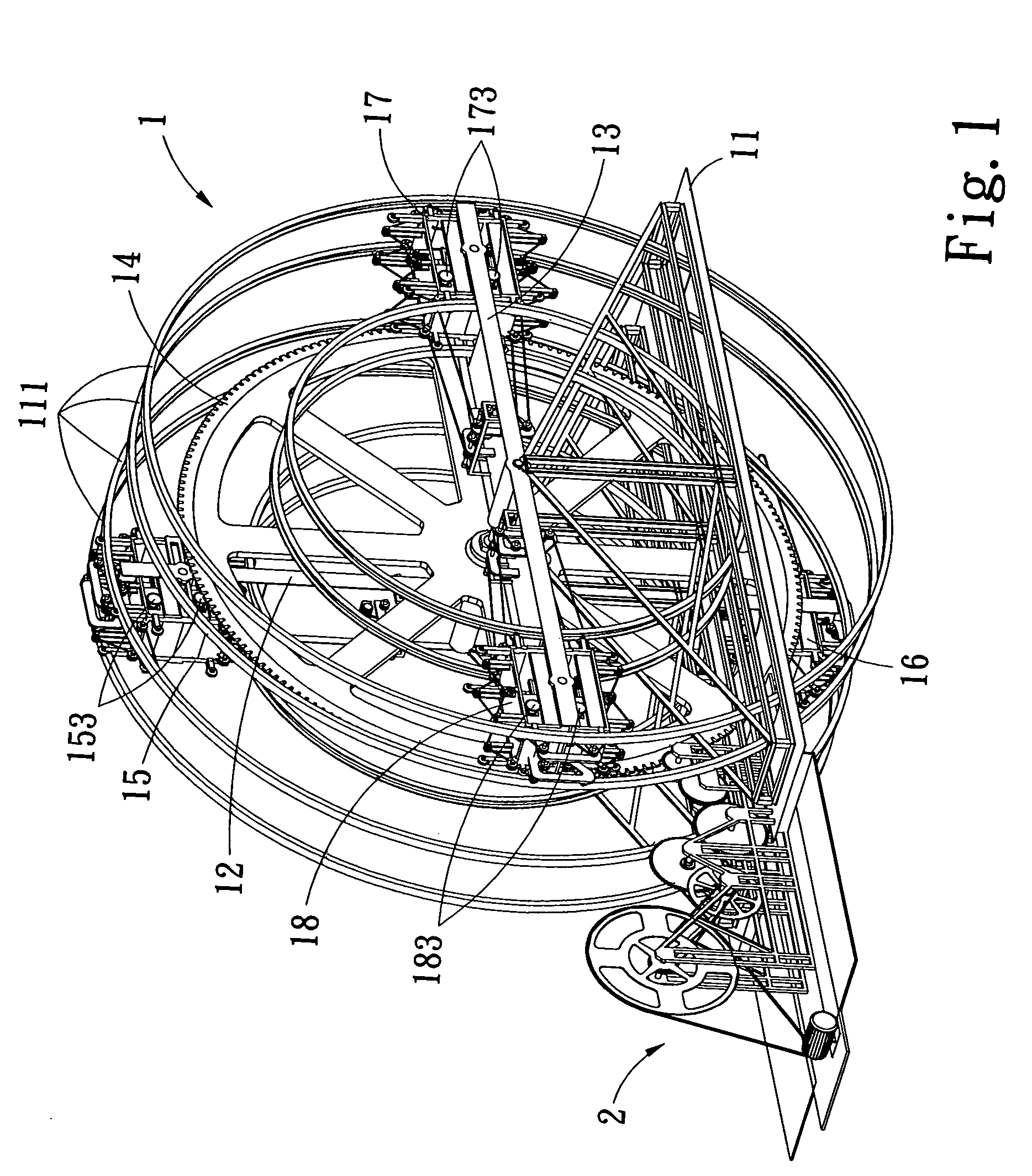
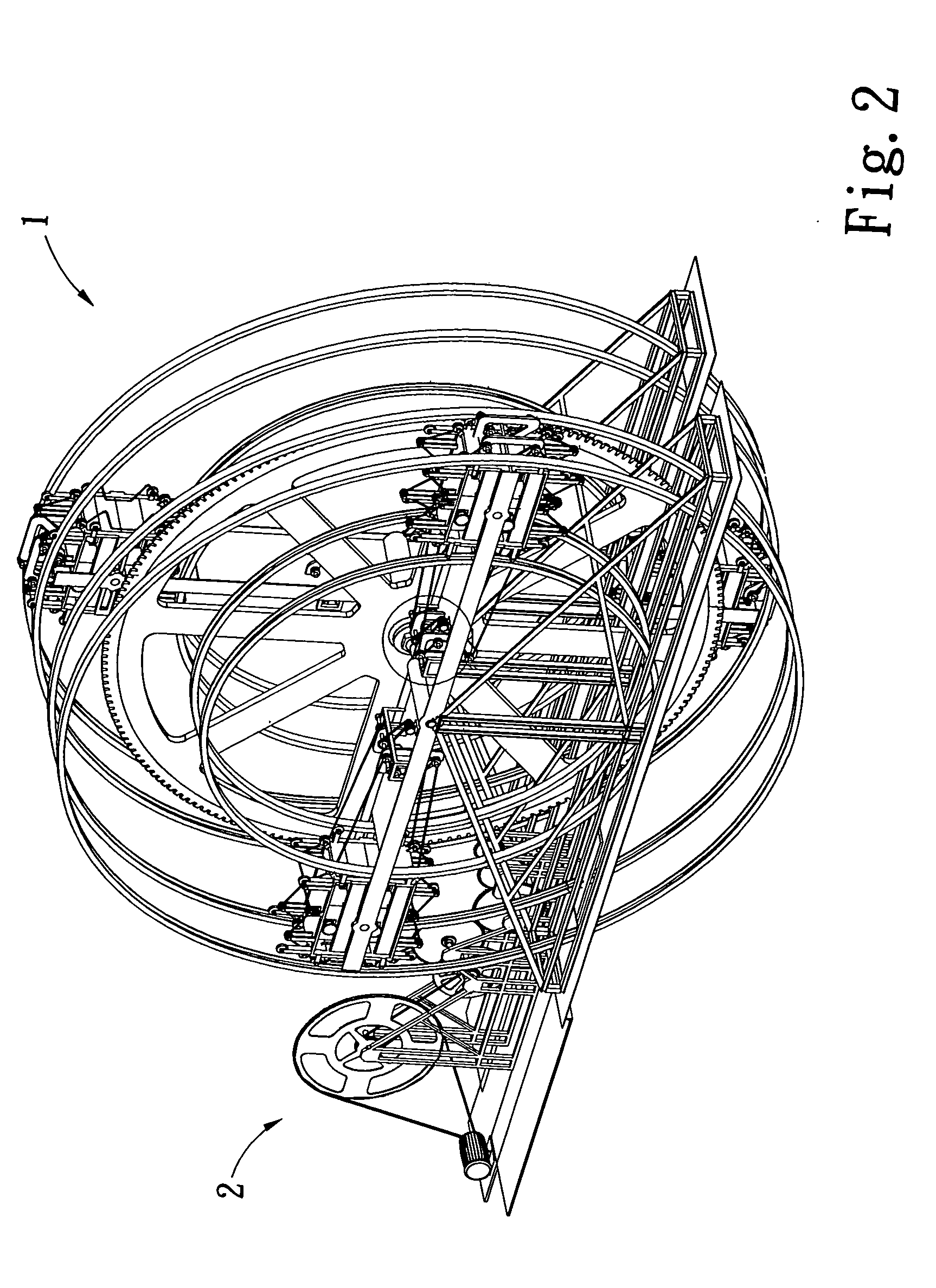
[0012] Referring to FIGS. 1 to 4, the energy generating mechanism of the present invention comprises an energy producing device 1 and an energy collection device 2 which includes a plurality of gears 21, wheels 22, belts 23 and an energy collection member 24 so as to collect the energy produced by the energy producing device 1.

[0013] The energy producing device 1 includes a truss 11, a first link 12 and a second link 13 are pivotably and perpendicularly connected with each other and are connected thereon to the truss 11. 2. A main gear 14 is co-axially connected to a pivotable axis of the first and second links 12, 13 and operationally connected to the energy collection device 2. Each of the first link 12 and the second link 13 has two boxes 15, 16 and 17,18 respectively on two ends thereof so as to balance the first and second links 12, 13. Each box 15,16,17,18 has blocks 151,161,171,181 movably received therein and rails 152, 162, 172, 182. Each box 15,16,17,18 further includes a...


PUM


Abstract

An energy generating mechanism includes an energy producing device and an energy collection device for collecting energy produced from the energy producing device. The energy producing device includes a truss, a first link and a second link which is pivotably perpendicularly connected to the first link on the truss. Each of the first link and the second link has two boxes on two ends thereof and each box has blocks movably received therein. The first and second links rotate continuously by changing the positions of the blocks so as

Description

FIELD OF THE INVENTION [0001] The present invention relates to an energy generating mechanism which generates energy by rotating two links continuously and the energy is collected by an energy collection device. BACKGROUND OF THE INVENTION [0002] Human consumes energy in a mass scale and the remained energy source on earth reaches a critical point which substantially threatens the living of human beings. Although wind power, solar power, hydro power and even the earth heat are developed to generate energy, the geographic conditions limits the use of the energy. It is a beginning stage for using the nature power and we have a long way to run before the nature power can be dominated by human beings. [0003] The present invention intends to provide an energy generating mechanism that includes two perpendicular links and two boxes are located on two ends of each links and each box includes blocks movably therein so that the links be continuously rotate by changing the positions of the bl...

Claims


Application Information

Patent Timeline
IPC IPC(8): F03G3/00
CPCF03G7/10F03G3/02
Inventor CHIU, CHIH-HO
Owner CHIU CHIH HO
Why Eureka
Try Eureka