

Method and apparatus for energy harvesting using microfluidics
a microfluidic and energy harvesting technology, applied in mechanical equipment, generators/motors, machines/engines, etc., can solve the problems of constant increasing strain on the available power source of such systems, affecting the power output of energy harvesters, and affecting the efficiency of energy harvesters
- Summary
- Abstract
- Description
- Claims
- Application Information
AI Technical Summary
Problems solved by technology
Method used
Image

Examples
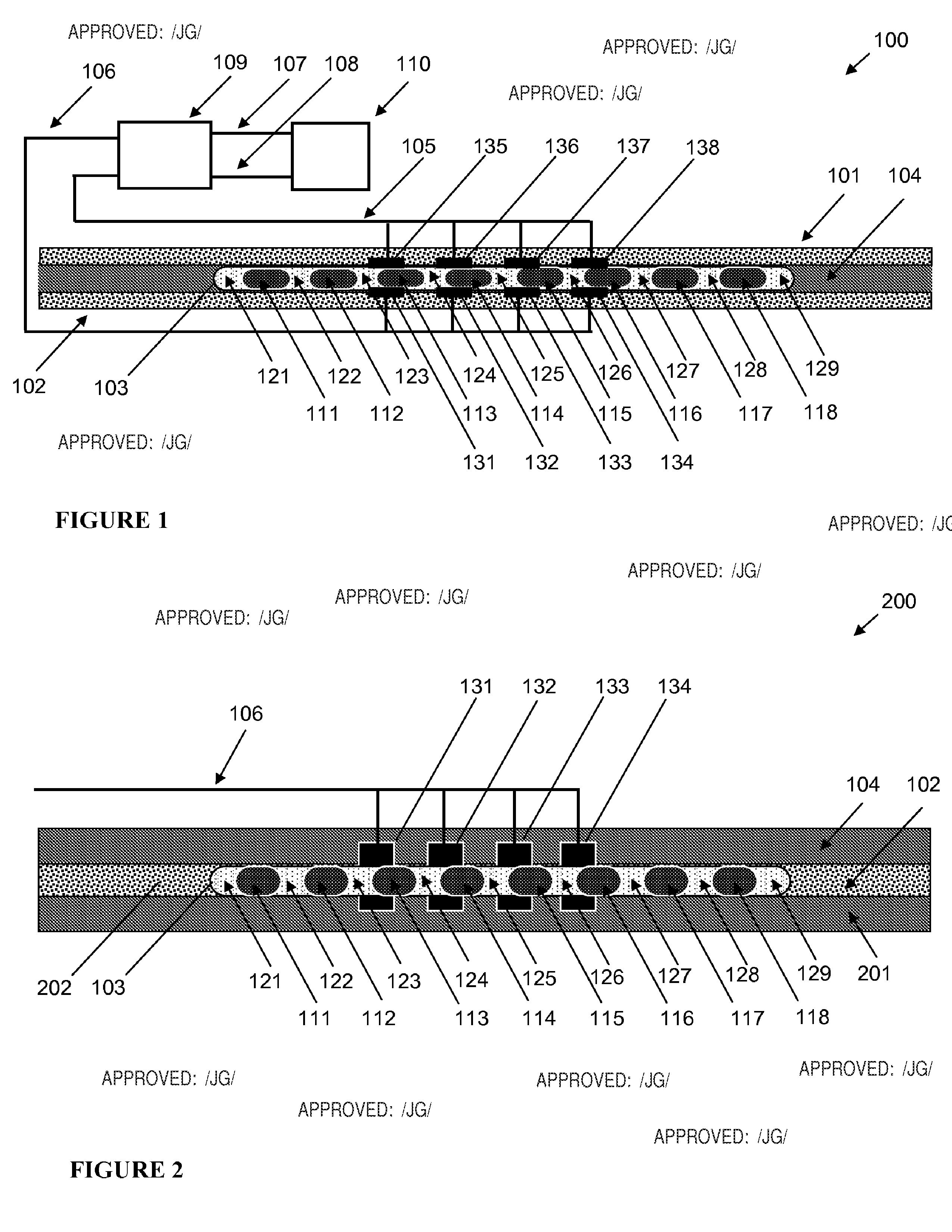
exemplary embodiment 100
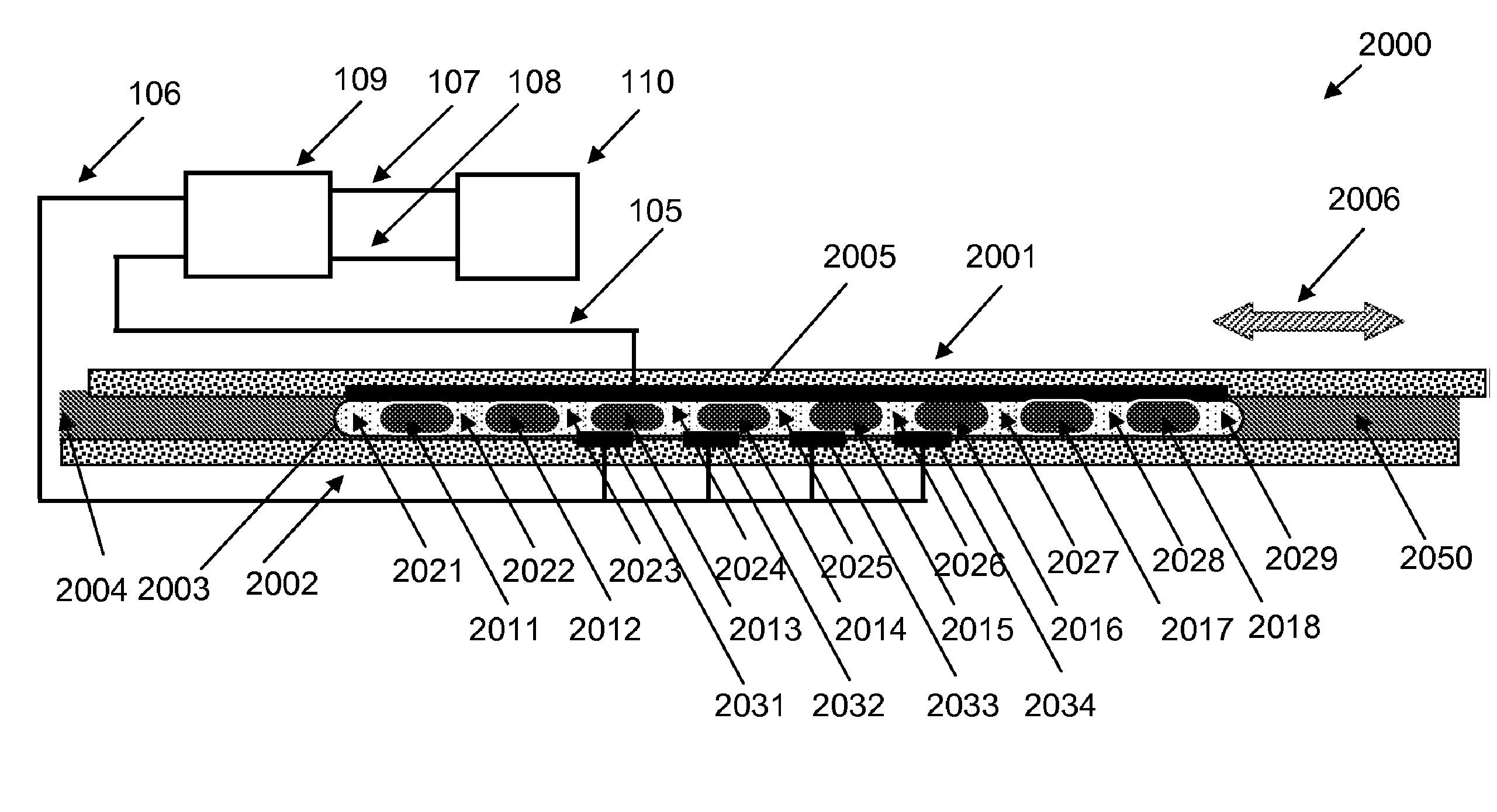
[0063]Quite obviously the same evolution of capacitance occurs at each pair of opposite electrodes, i.e. at electrodes 131 and 135, electrodes 132 and 136, electrodes 133 and 137, and electrodes 134 and 138. Since all these pairs of electrodes are connected in parallel, one can treat the entire set of electrodes electrically coupled to connectors 105 and 106 as one variable capacitor with the total capacitance C equal to NC0, where N is a number of electrode pairs, e.g. N=4 for exemplary embodiment 100. The movement of fluidic body 103 along the channel 202 causes multiple variations of the total capacitance C between zero and some maximum value Cm.
[0064]There are a number of methods that can be used to extract electrical energy from a variable capacitor with alternating in time capacitance and that can be adapted for use with the current invention. Some of those methods are disclosed in U.S. Pat. Nos. 6,936,994, 4,127,804, 6,127,812, 3,094,653, 3,013,201, 4,054,826, 6,750,590, 4,89...
exemplary embodiment 1200
[0075]FIG. 12 presents cross-sectional view of a forth exemplary embodiment 1200 of an apparatus for converting mechanical energy into electrical energy. FIG. 13 presents a plan view of a part 1300 of the same apparatus, where parts 101, 105, 107, 108, 109, 110, 1201 of apparatus 1200 are removed and spacers 104 and 201 are rendered semitransparent for the clarity of presentation. For simplicity, FIG. 12 and FIG. 13 present electrical connectors only schematically, not reflecting their actual physical arrangement.
[0076]The main difference between apparatus 1200 and previously described apparatus 100 is the absence of separate electrodes 135, 136, 137, 138 disposed on substrate 101. Instead, one common electrode 1201 is disposed on substrate 101. FIG. 14 presents a close-up cross-sectional view of a part 1400 of apparatus 1200. It can be seen in FIG. 14 that substrate 101 and electrode 1201 are covered by only one layer 302, while substrate 102 and electrodes 131, 132, 133, 134 is co...
exemplary embodiment 1600
[0077]FIG. 16 presents cross-sectional view of a fifth exemplary embodiment 1600 of an apparatus for converting mechanical energy into electrical energy. FIG. 17 presents a plan view of a part 1700 of the same apparatus, where parts 101, 105, 1607, 1608, 1609, 1610, 1201 of apparatus 1600 are removed and spacers 104 and 201 are rendered semitransparent for the clarity of presentation. For simplicity, FIG. 16 and FIG. 17 present electrical connectors only schematically, not reflecting their actual physical arrangement.
[0078]The arrangement of apparatus 1600 is similar to that of apparatus 1200. The apparatus 1600 comprises two substrates 101 and 102 disposed substantially co-planar and separated by spacers 104 and 201. Spacers 104 and 201 are disposed in such a way as to form a channel 202. One common electrode 1201 is disposed on substrate 101 and a plurality of electrodes 1631, 1632, 1633, 1634 is disposed on substrate 102. Similar to apparatus 1200 and apparatus 100 substrates 101...
PUM
 Abstract
Description
Claims
Application Information