Microfluidic design automation method and system

a microfluidic and design automation technology, applied in memory systems, program control, special data processing applications, etc., can solve the problems of time-consuming and costly design and manufacturing conventional computer aided design tools such as autocad® are inadequate for the design and layout of such microfluidic systems, so as to reduce errors, reduce time, and facilitate placement and routing

Inactive Publication Date: 2005-03-24
FLUIDIGM CORP
View PDF99 Cites 83 Cited by
  • Summary
  • Abstract
  • Description
  • Claims
  • Application Information

AI Technical Summary

Benefits of technology

An advantage of the present invention is the reduction in time needed to complete the design and implementation of a microfluidic circuit. For example, in one embodiment of the present invention, synthesis, schematic capture, and functional simulation allow an efficient and expedient process of creating and validating an initial design, the physical layout tool allows easy placement and routing of multilayered components on a predefined template, the physical simulation allows the reduction in errors before fabrication, and the die placement tool allows faster wafer mask generation.
is the reduction in time needed to complete the design and implementation of a microfluidic circuit. For example, in one embodiment of the present invention, synthesis, schematic capture, and functional simulation allow an efficient and expedient process of creating and validating an initial design, the physical layout tool allows easy placement and routing of multilayered components on a predefined template, the physical simulation allows the reduction in errors before fabrication, and the die placement tool allows faster wafer mask generation.
The uses and results generated by the present invention include cell based assays (including micro cell sorting, genomic analysis, such as DNA sizing, hybridization, sequencing, quantification, and amplification); protein analysis, crystallization and purification; MS-interface; biochemical and electrophysiological assays, gene expressions; differential display analysis; integrated biological sample preparation; single molecule analysis; drug delivery; diagnostics; and other uses and products related to the chemical, biochemical, biological, electronic, computer, appliance, pharmaceutical, medical, or power industries.

Problems solved by technology

Because different protocols require different configurations, the design and manufacturing of such microfluidic systems can be time-consuming and costly.
Conventional computer aided design tools such as AutoCAD® are inadequate for the design and layout of microfluidic systems.

Method used


Image

  • Microfluidic design automation method and system
  • Microfluidic design automation method and system
  • Microfluidic design automation method and system

Examples


Embodiment Construction

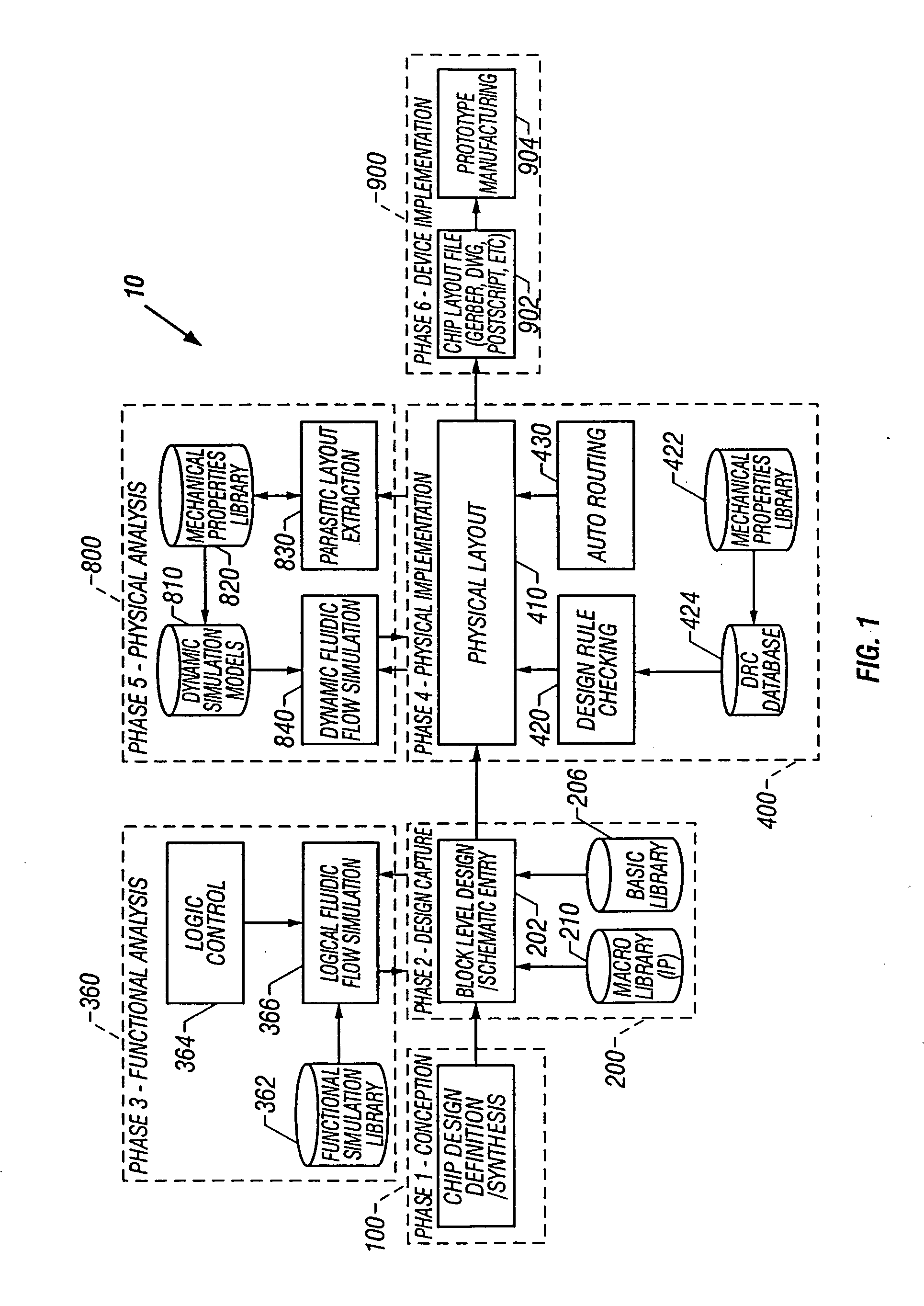
Embodiments of the present invention are directed to the design of customized microfluidic systems using a microfluidic computer aided design (MCAD) system. The MCAD system provides the user with the tools to design, analyze, and implement a customized microfluidic system using a plurality of building block microfluidic components.

In one embodiment of the invention, the MCAD system includes a design capture module including a schematic entry tool for selecting and connecting microfluidic components according to a design. The system further includes a functional analysis module for functionally simulating selected microfluidic components of the design, a physical implementation module for arranging the microfluidic components into a physical layout according to the design, and a physical analysis module for physically simulating the microfluidic components in the physical layout.

In some embodiments, the modules comprise computer instructions or code stored in a computer-readable...


PUM

PropertyMeasurementUnit
sizeaaaaaaaaaa
sizeaaaaaaaaaa
widthaaaaaaaaaa

Abstract

The present invention generally relates to microfluidics and more particularly to the design of customized microfluidic systems using a microfluidic computer aided design system. In one embodiment of the present invention a microfluidic circuit design method is provided. The method includes developing synthesizable computer code for a design. Next, a microfluidic circuit schematic, including a plurality of symbols for microfluidic components, is generated either interactively or using the synthesizable computer code. The microfluidic circuit schematic is then functionally simulated. The microfluidic components are placed and routed on a template to form a physical layout. Then the physical layout is physically simulated using dynamic simulation models of the microfluidic components; and the physical layout is written to a layout file.

Description

BACKGROUND OF THE INVENTION The present invention generally relates to microfluidics and more particularly to the design of customized microfluidic systems using a microfluidic computer aided design system. Such customized microfluidic systems may be used, for example, for fluid analysis of biological samples. Typically microfluidic systems for processing fluid samples employ a series of chambers each configured for subjecting the fluid sample to a specific processing step. As the fluid sample flows through the system sequentially from chamber to chamber, the fluid sample undergoes the processing steps according to a specific protocol. Because different protocols require different configurations, the design and manufacturing of such microfluidic systems can be time-consuming and costly. Conventional computer aided design tools such as AutoCAD® are inadequate for the design and layout of microfluidic systems. For instance, AutoCAD® is a general tool, and has no drawing constraints...

Claims


Application Information

Patent Timeline
Patent Type & Authority Applications(United States)
IPC IPC(8): B01F13/00B01F15/00B01L3/00B81B1/00B81C99/00G06F17/50
CPCB01F13/0059B01F15/00824B01F15/00935B01J2219/00997B01L3/5027B01L3/502707H01H2029/008B01L2200/12B81B1/00B81C99/006G06F17/509G06F2217/16B01L3/502715G06F30/18G06F2111/10B01F33/30B01F35/50B01F35/561G06F30/00G06F2115/04
Inventor LEE, MICHAELWORTHINGTON, GAJUSHARRIS, GREGORYMONTGOMERY, JAMES
Owner FLUIDIGM CORP
Why Eureka
Try Eureka