Actuators for microfluidics without moving parts

a technology of microfluidics and actuators, which is applied in the direction of flow mixers, electrolysis, diaphragms, etc., can solve the problems of inability to manipulate droplets, poor reproducibility of both methods, and inability to provide ink jetting technology with means to manipulate droplets, etc., to achieve the effect of maximizing the overlap area

Inactive Publication Date: 2007-11-22
ADVANCED LIQUID LOGIC
View PDF9 Cites 85 Cited by
  • Summary
  • Abstract
  • Description
  • Claims
  • Application Information

AI Technical Summary

Benefits of technology

[0014] The operating principle of the devices is known as electrowetting. If a droplet of polar conductive liquid is placed on a hydrophobic surface, application of electric potential across the liquid-solid interface reduces the contact angle, effectively converting the surface into more hydrophilic. According to the present invention, the electric fields effecting the hydrophobic-hydrophilic conversion are controlled by applying an electrical potential to electrodes arranged as an array on at least one side of the gap. The electrodes on the other side may or may not be arranged in a similar array; in the preferred embodiment, there is array of electrodes only on one side of the gap, while the other has only one large electrode covering substantially the entire area of the device.
[0016] By applying an electrical potential to an electrode or a group of electrodes adjacent to an area contacted by polar liquid, the hydrophobic surface on top of these electrodes is converted to hydrophilic and the polar liquid is pulled by the surface tension gradient (Marangoni effect) so as to maximize the area overlap with the charged group of electrodes.

Problems solved by technology

Both methods suffer poor reproducibility.
While ink jetting is a dispensing method generally applicable to a wide variety of liquids, the volume of the deposited droplets is not very stable.
Ink jetting technology does not provide means to manipulate droplets after they have been deposited on the surface, except for removing them.
While this feature of electromigration methods is, useful for analytical purposes, because it allows physical separation of components of mixtures, it is undesirable in general micromanipulation techniques.
Additionally, the need to pass electrical current through the liquid results in heating of the liquid, which may cause undesirable chemical reactions or even boiling.
To avoid this, the electrical conductivities of all liquids in the system are kept low, limiting the applicability of electromigration methods.
This requirement additionally complicates precision dispensing and results in ineffective use of reagents, because the metered doses of a liquid are isolated from a continuous flow of that liquid from one electrode to another.

Method used


Image

  • Actuators for microfluidics without moving parts
  • Actuators for microfluidics without moving parts
  • Actuators for microfluidics without moving parts

Examples


example 1

A Pump

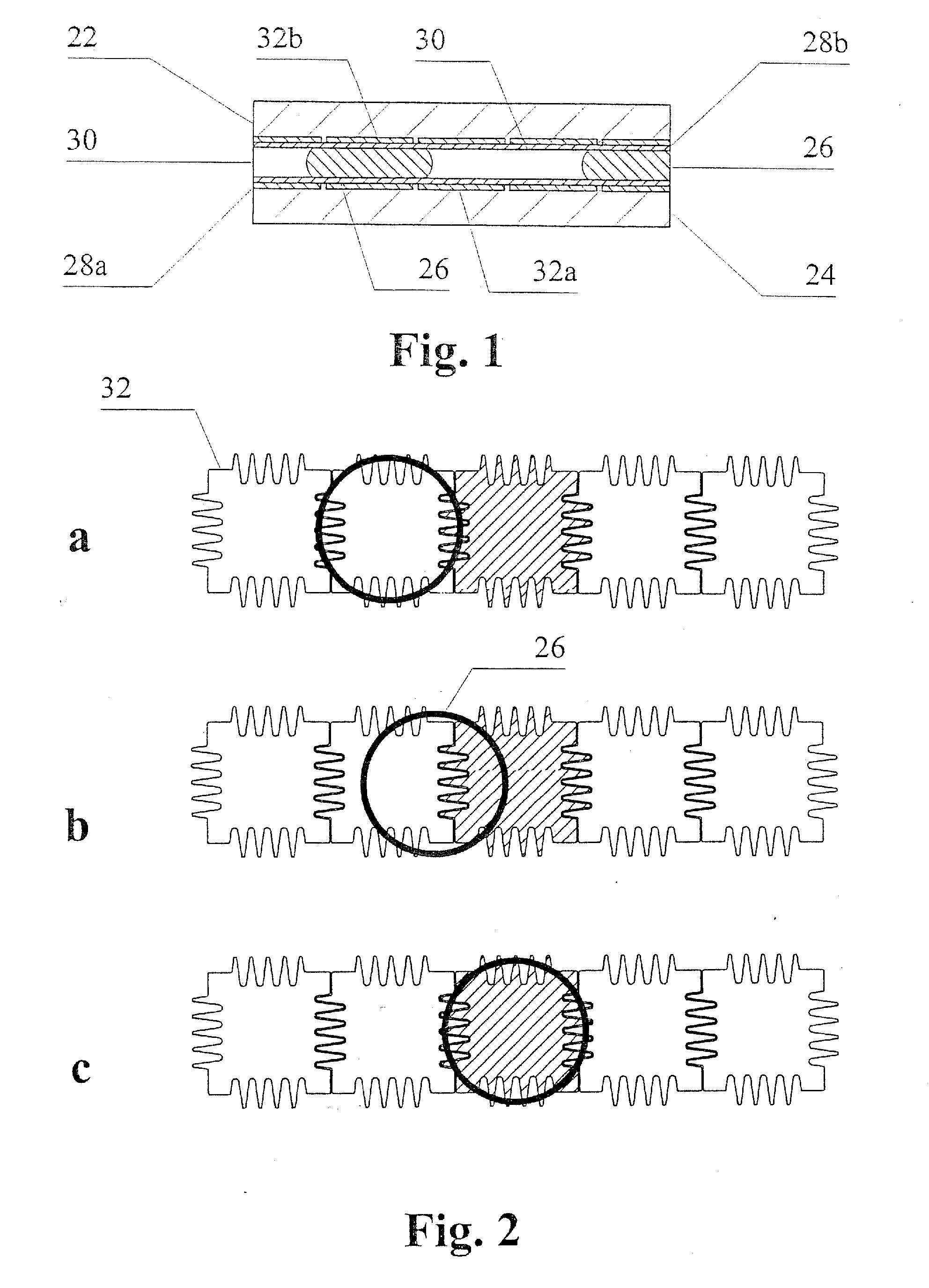
[0055] The linear arrangement of electrodes shown in FIG. 2 is an integral pump. A droplet of polar liquid, or a streak of several electrode lengths, can be moved along by applying a wetting potential to an electrode on one side of it and removing the wetting potential from the last electrode under the other side of the streak.

[0056] To aid the effect of electrowetting in moving liquid from one electrode to another, in a preferred embodiment the gap separating two adjacent electrodes is not straight. Preferably, it has either sawtooth or meander shape, preferably with rounded corners. The depths and widths of the interdigitated features of the adjacent electrodes are preferably chosen so as to promote moving liquid from one electrode to another when the voltage is applied to the latter electrode, as shown in FIG. 2 a-c. The initial position of the droplet 26 is shown in FIG. 2a. The hatching of an electrode 32 adjacent to the position of the droplet indicates that that elect...

example 2

A Drop Meter

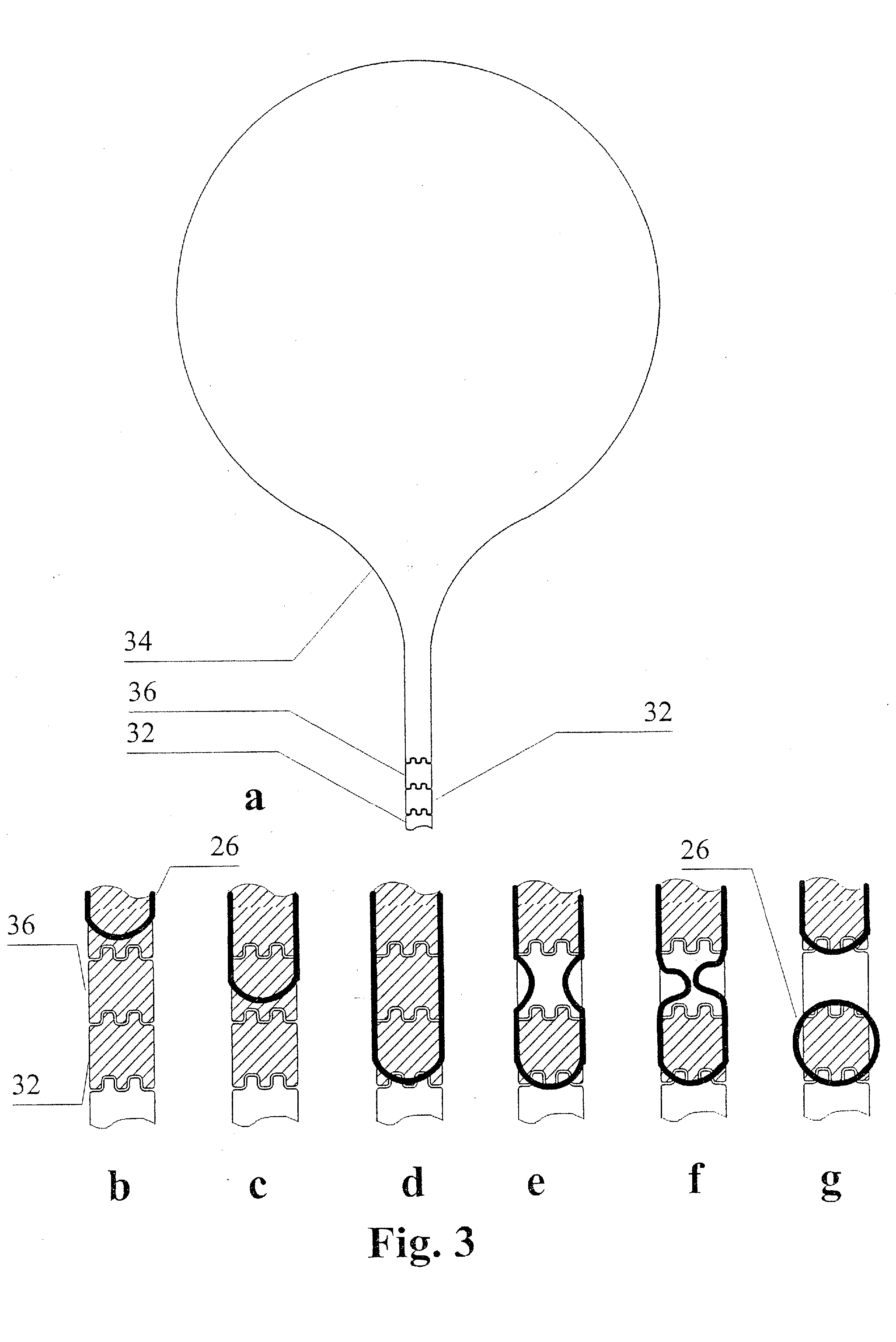
[0057] As a convenient interface between a microfluidics device operating in subnanoliter to microliter range of volumes with the outside world, a drop meter is provided. The drop meter comprises an arrangement control pads on one side of the chamber (FIG. 3a). The contact pad 34 is either hydrophilic due to material it is made of, or due to a surface treatment, or made hydrophilic by applying a wetting potential to an underlying electrode. The other two control pads have electrodes under the hydrophobic surface.

[0058] To operate the drop meter, a wetting potential is first applied to the cutoff electrode 36 and the control electrode 32. As a result of this, the liquid which has covered the surface of the contact pad 34 spreads over the other two pads, 32 and 36 (FIG. 3 b-d). Consequently, the wetting potential is removed from the cutoff electrode 36, making it hydrophobic again. Part of the liquid moves back to the contact pad 34, and is replaced on the cutoff electro...

example 3

An Active Reservoir

[0059] A reagent solution may be stored in an active reservoir in a sealed device and delivered under electronic control to a reaction site. An example of such reservoir is shown in FIG. 4. The delivery is effected by applying the wetting potential to the first electrode 32 of the transport line and removing the potential sequentially from the reservoir electrodes 40, for example beginning from the corner(s) furthermost from the transport line. To allow for long storage of the devices with power off, the coating within the reservoir area is only moderately hydrophobic, and the rim 38 around that area is extremely hydrophobic. The polar liquid will not spill beyond the rim 38, allowing long shelf life of the device.


PUM

PropertyMeasurementUnit
hydrophilicaaaaaaaaaa
hydrophilic characteraaaaaaaaaa
voltageaaaaaaaaaa

Abstract

A series of microactuators for manipulating small quantities of liquids, and methods of using these for manipulating liquids, are disclosed. The microactuators are based on the phenomenon of electrowetting and contain no moving parts. The force acting on the liquid is a potential-dependent gradient of adhesion energy between the liquid and a solid insulating surface.

Description

CROSS REFERENCES TO RELATED APPLICATIONS [0001] This application is a divisional of U.S. patent application Ser. No. 10 / 430,816, filed May 6, 2003, which is a divisional of U.S. patent application Ser. No. 09 / 490,769, filed Jan. 14, 2000, which claims the benefit of provisional patent application No. 60 / 117,002, filed Jan. 25, 1999.FIELD OF THE INVENTION [0002] This invention relates generally to the fields of laboratory automation, microfabrication and manipulation of small volumes of fluids (microfluidics), in such a manner so as to enable rapid dispensing and manipulation of small isolated volumes of fluids under direct electronic control. More specifically, the invention relates to a method of forming and moving individual droplets of electrically conductive liquid, and devices for carrying out this method. BACKGROUND OF THE INVENTION [0003] Miniaturization of assays in analytical biochemistry is a direct result of the need to collect maximum data from a sample of a limited volu...

Claims


Application Information

Patent Timeline
Patent Type & Authority Applications(United States)
IPC IPC(8): G01N27/00B01F5/00B01F13/00B01L3/00F04B17/00F04B19/00
CPCB01F13/0071G02B26/005B01F2005/0017B01L3/502738B01L3/502746B01L3/502784B01L3/502792B01L2200/0673B01L2200/10B01L2200/16B01L2300/0816B01L2300/0819B01L2300/0867B01L2300/089B01L2400/0415B01L2400/0427F04B17/00F04B19/006F16K99/0001F16K99/0017B01F13/0076B01F2025/913B01F33/3021B01F33/3031
Inventor SHENDEROV, ALEXANDER DAVID
Owner ADVANCED LIQUID LOGIC
Why Eureka
Try Eureka