Method of using actuators for microfluidics without moving parts
a technology of actuators and microfluidics, which is applied in the direction of flow mixers, electrolysis, diaphragms, etc., can solve the problems of poor reproducibility of both methods, inability to provide means for manipulating droplets, and unstable volume of deposited droplets, so as to achieve the effect of maximizing the overlap area
- Summary
- Abstract
- Description
- Claims
- Application Information
AI Technical Summary
Benefits of technology
Problems solved by technology
Method used
Image
Examples
example 1
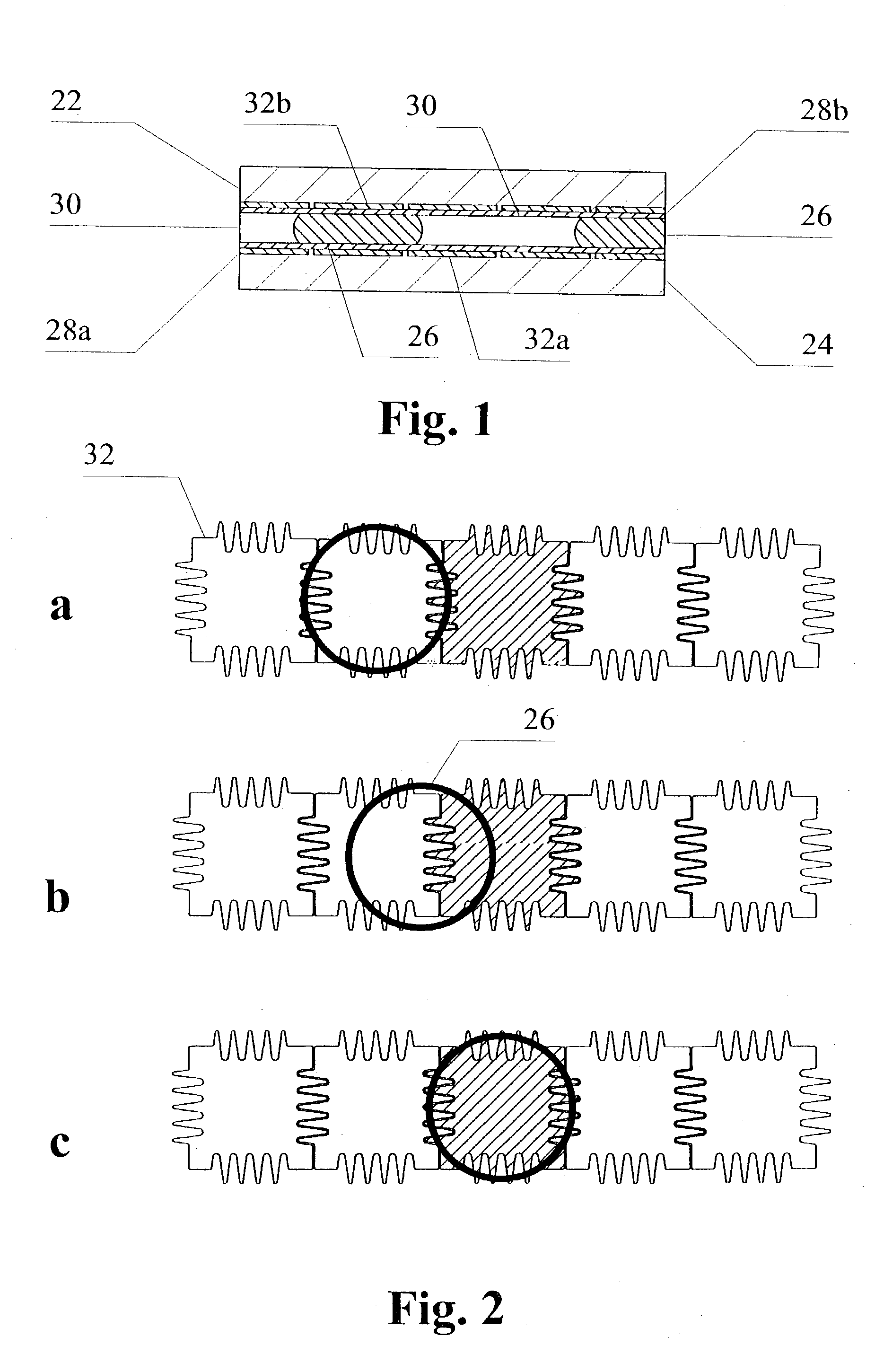
[0055]The linear arrangement of electrodes shown in FIG. 2 is an integral pump. A droplet of polar liquid, or a streak of several electrode lengths, can be moved along by applying a wetting potential to an electrode on one side of it and removing the wetting potential from the last electrode under the other side of the streak.
[0056]To aid the effect of electrowetting in moving liquid from one electrode to another, in a preferred embodiment the gap separating two adjacent electrodes is not straight. Preferably, it has either sawtooth or meander shape, preferably with rounded corners. The depths and widths of the interdigitated features of the adjacent electrodes are preferably chosen so as to promote moving liquid from one electrode to another when the voltage is applied to the latter electrode, as shown in FIGS. 2a–c. The initial position of the droplet 26 is shown in FIG. 2a. The hatching of an electrode 32 adjacent to the position of the droplet indicates that that electrode is co...
example 2
ter
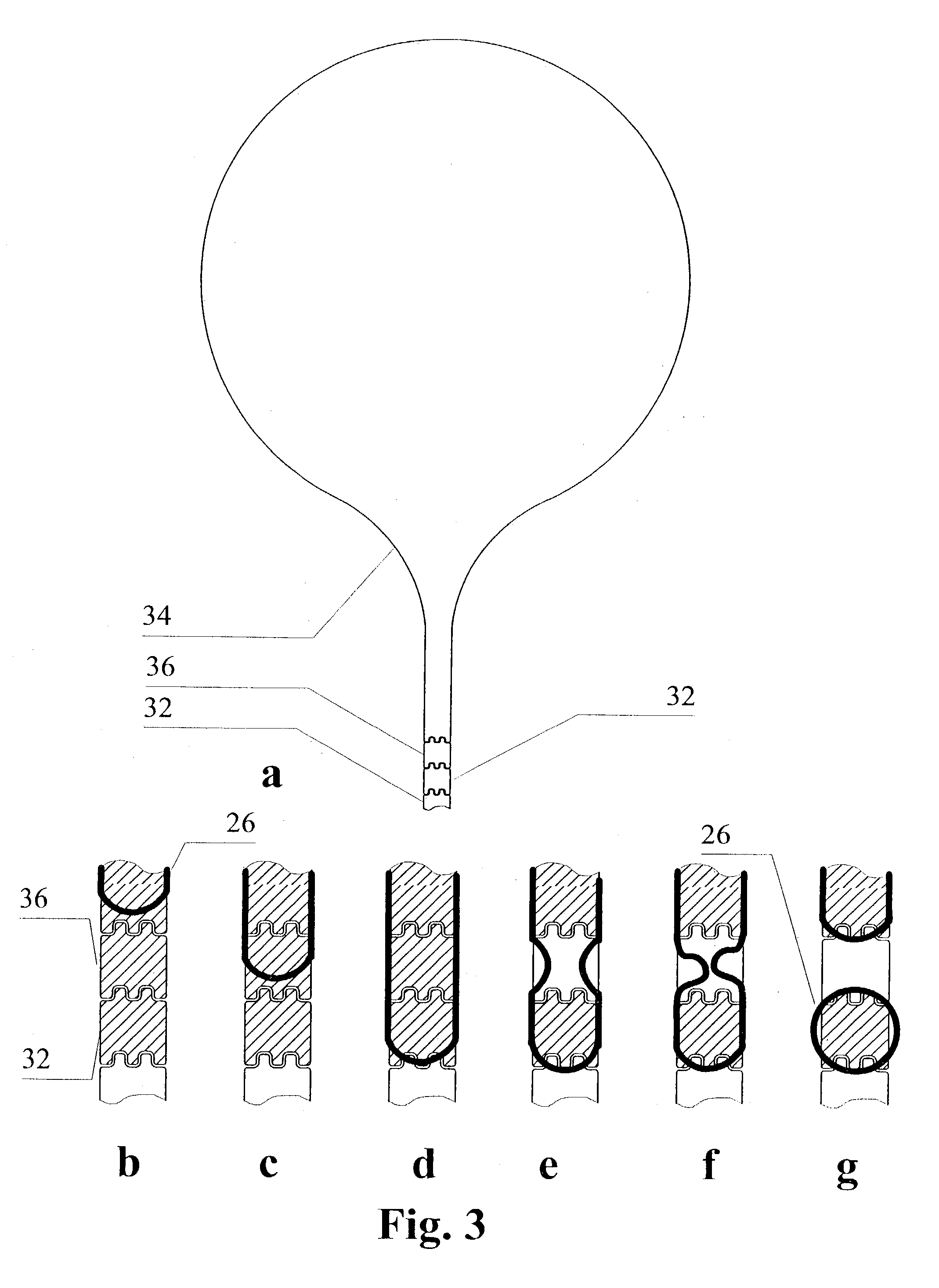
[0057]As a convenient interface between a microfluidics device operating in subnanoliter to microliter range of volumes with the outside world, a drop meter is provided. The drop meter comprises an arrangement control pads on one side of the chamber (FIG. 3a). The contact pad 34 is either hydrophilic due to material it is made of, or due to a surface treatment or made hydrophilic by applying a wetting potential to an underlying electrode. The other two control pads have electrodes under the hydrophobic surface.
[0058]To operate the drop meter, a wetting potential is first applied to the cutoff electrode 36 and the control electrode 32. As a result of this, the liquid which has covered the surface of the contact pad 34 spreads over the other two pads, 32 and 36 (FIGS. 3b–d). Consequently, the wetting potential is removed from the cutoff electrode 36, making it hydrophobic again. Part of the liquid moves back to the contact pad 34, and is replaced on the cutoff electrode 36 with the...
example 3
reservoir
[0059]A reagent solution may be stored in an active reservoir in a sealed device and delivered under electronic control to a reaction site. An example of such reservoir is shown in FIG. 4. The delivery is effected by applying the wetting potential to the first electrode 32 of the transport line and removing the potential sequentially from the reservoir electrodes 40, for example beginning from the corner(s) furthermost from the transport line. To allow for long storage of the devices with power off, the coating within the reservoir area is only moderately hydrophobic, and the rim 38 around that area is extremely hydrophobic. The polar liquid will not spill beyond the rim 38, allowing long shelf life of the device.
PUM
| Property | Measurement | Unit |
|---|---|---|
| Energy | aaaaa | aaaaa |
Abstract
Description
Claims
Application Information
 - R&D
- Intellectual Property
- Life Sciences
- Materials
- Tech Scout
- Unparalleled Data Quality
- Higher Quality Content
- 60% Fewer Hallucinations
Browse by: Latest US Patents, China's latest patents, Technical Efficacy Thesaurus, Application Domain, Technology Topic, Popular Technical Reports.
© 2025 PatSnap. All rights reserved.Legal|Privacy policy|Modern Slavery Act Transparency Statement|Sitemap|About US| Contact US: help@patsnap.com


