System for optimal energy harvesting and storage from an electromechanical transducer

Active Publication Date: 2006-09-12
POLATIS PHOTONICS INC
View PDF22 Cites 120 Cited by
  • Summary
  • Abstract
  • Description
  • Claims
  • Application Information

AI Technical Summary

Benefits of technology

[0005]The present invention differentiates itself from the prior art because it proposes a system and electrical circuit that can be used to efficiently harvest, store and transfer power from mechanical disturbances, and then apply that power to an applic

Problems solved by technology

Often, the voltage range that is optimal for collecting energy from an electromechanical transducer is not compatible with the requirements of low power circuit loads.
Since the ave

Method used


Image

  • System for optimal energy harvesting and storage from an electromechanical transducer
  • System for optimal energy harvesting and storage from an electromechanical transducer
  • System for optimal energy harvesting and storage from an electromechanical transducer

Examples


Embodiment Construction

[0022]A description of preferred embodiments of the invention follows.

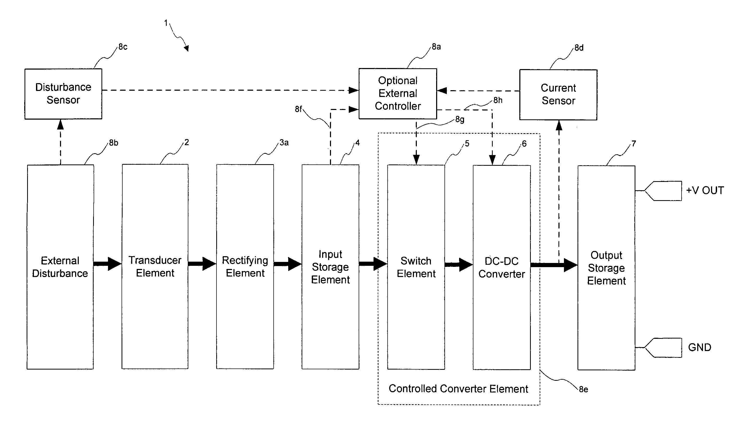
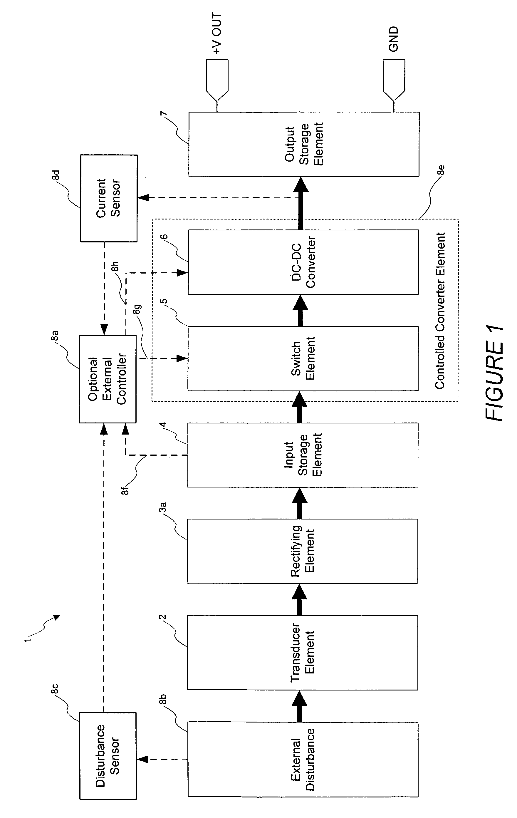
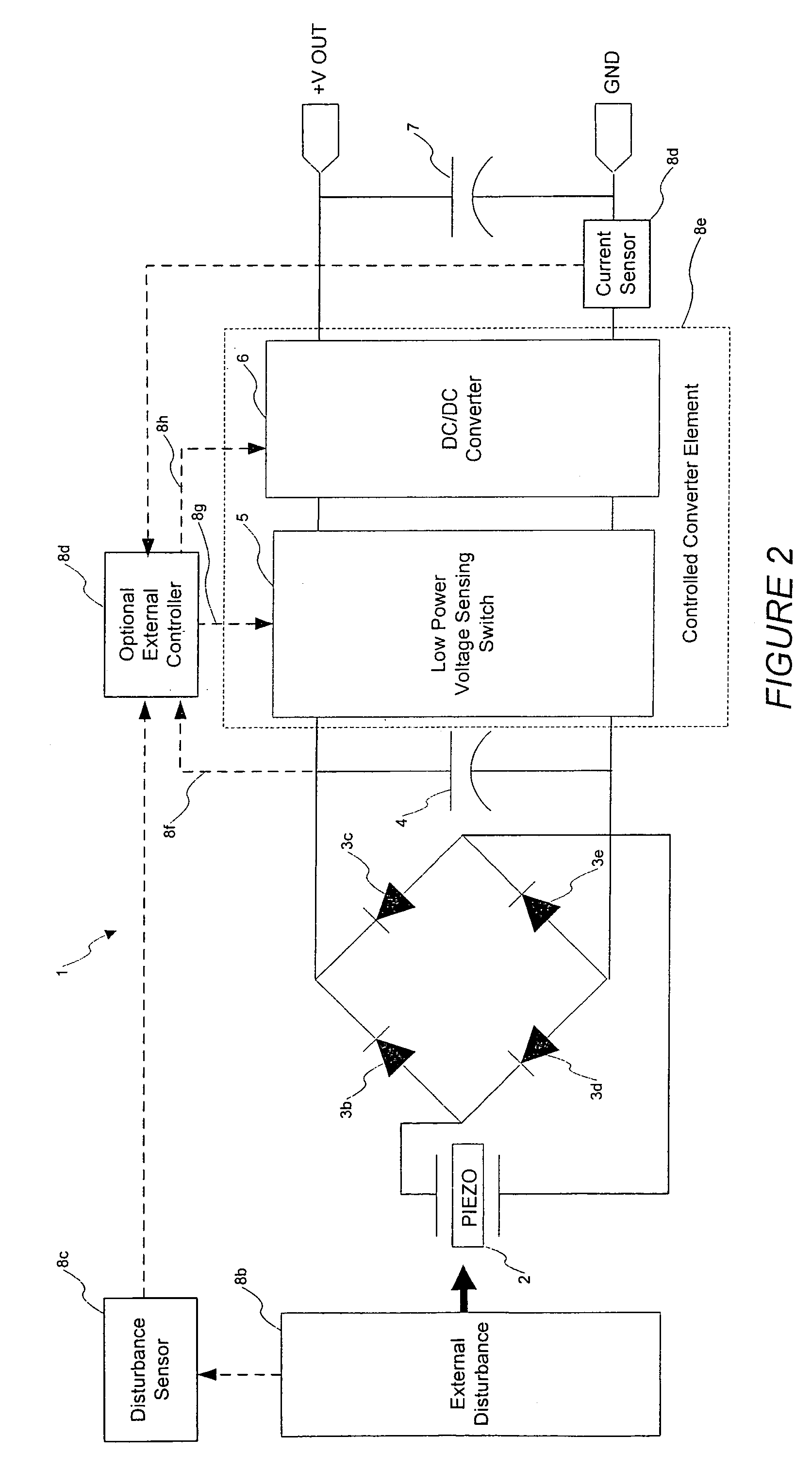
[0023]The invention relates to an electrical circuit for optimally harvesting, storing and transferring power generated by mechanical disturbances to an electrical load. The power harvesting circuit efficiently collects and stores energy from mechanical disturbances in an input storage element. The accumulated energy is then converted using a controlled DC—DC converter to the optimal voltage level for the load electronics. The circuit invention thus accumulates and stores energy in the optimal voltage range of the transducer, while delivering the energy at the optimal voltage for the final load at the optimal output voltage.

[0024]A block diagram of one embodiment of the invention is shown in FIG. 1. The circuit 1 is coupled to consists of a mechanical disturbance 8b, and included a electromechanical (possibly piezoelectric) transducer 2, a rectifying bridge made up of diodes 3a, an input storage element 4, a contr...


PUM


Abstract

A device for collection of energy from mechanical disturbances and distribution of that energy to an electrical load. A transducer converts mechanical energy in the form of forces and displacements into electrical energy in the form of charge pulses. The charge pulses are rectified into a Direct Current (DC) power signal and accumulated and stored in an input storage element. A controlled conversion circuit assures that the voltage on the storage element is maintained within a predetermined optimal range for energy harvesting from the transducer, avoiding the application of peak voltages. The controlled conversion circuit can be hard wired and/or controllably adjustable to match a given disturbance characteristic. Only when the voltage is within the optimal range for a given type of disturbance will the controlled conversion circuit enable a DC/DC converter to further convert the stored energy to a voltage that is coupled to an output storage element. This technique optimizes power conversion by controlling the high voltage to low version conversion process by, for example, sensing the disturbance with external sensor or internal voltage of the system, and then using this information about the disturbance to control how and when the electrical conversion process will occur.

Description

RELATED APPLICATION(S)[0001]This application claims the benefit of U.S. Provisional Application No. 60 / 458,025, filed on Mar. 26, 2003. The entire teachings of the above application(s) are incorporated herein by reference.FIELD OF THE INVENTION[0002]The invention relates to systems and techniques for optimally harvesting, storing and transferring power generated by mechanical disturbances to an electrical load.BACKGROUND OF THE INVENTION[0003]Harvesting energy from intermittent mechanical disturbances can be of great value for powering remote sensors and other types of electrical circuits such as those supporting wireless transponders. Even if the available disturbances are relatively minor and produce only very small amounts of energy, the sum total of energy collected over time can be enormous benefit for a wide variety of applications. Energy harvesting transducers and energy storage circuitry can effectively provide “self powering circuits” that are far more robust and longer li...

Claims


Application Information

Patent Timeline
IPC IPC(8): H01L41/113
CPCH02N2/181
Inventor HAGOOD, IV, NESBITT WARDCOLTER, JEFFREY B.
Owner POLATIS PHOTONICS INC
Why Eureka
Try Eureka