Venturi vortex and flow facilitating turbine

Active Publication Date: 2020-02-06
MONTO MARK
View PDF0 Cites 6 Cited by
  • Summary
  • Abstract
  • Description
  • Claims
  • Application Information

AI Technical Summary

Benefits of technology

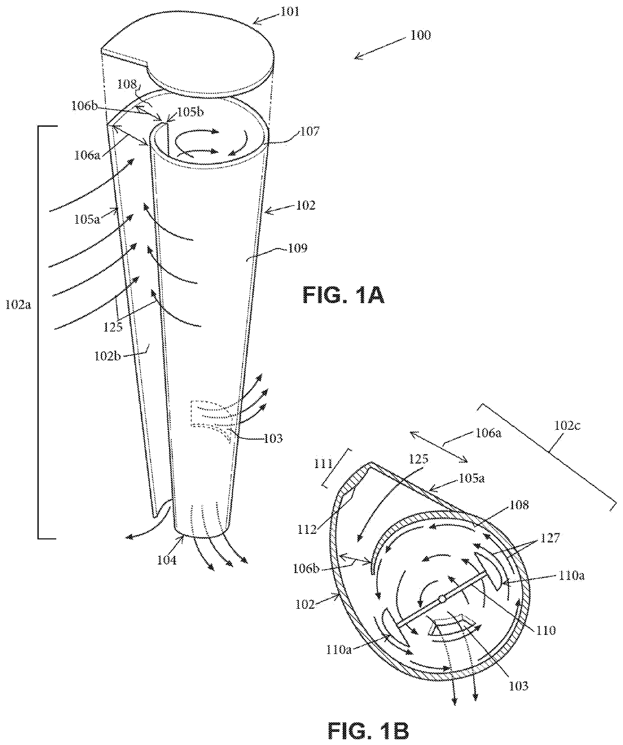
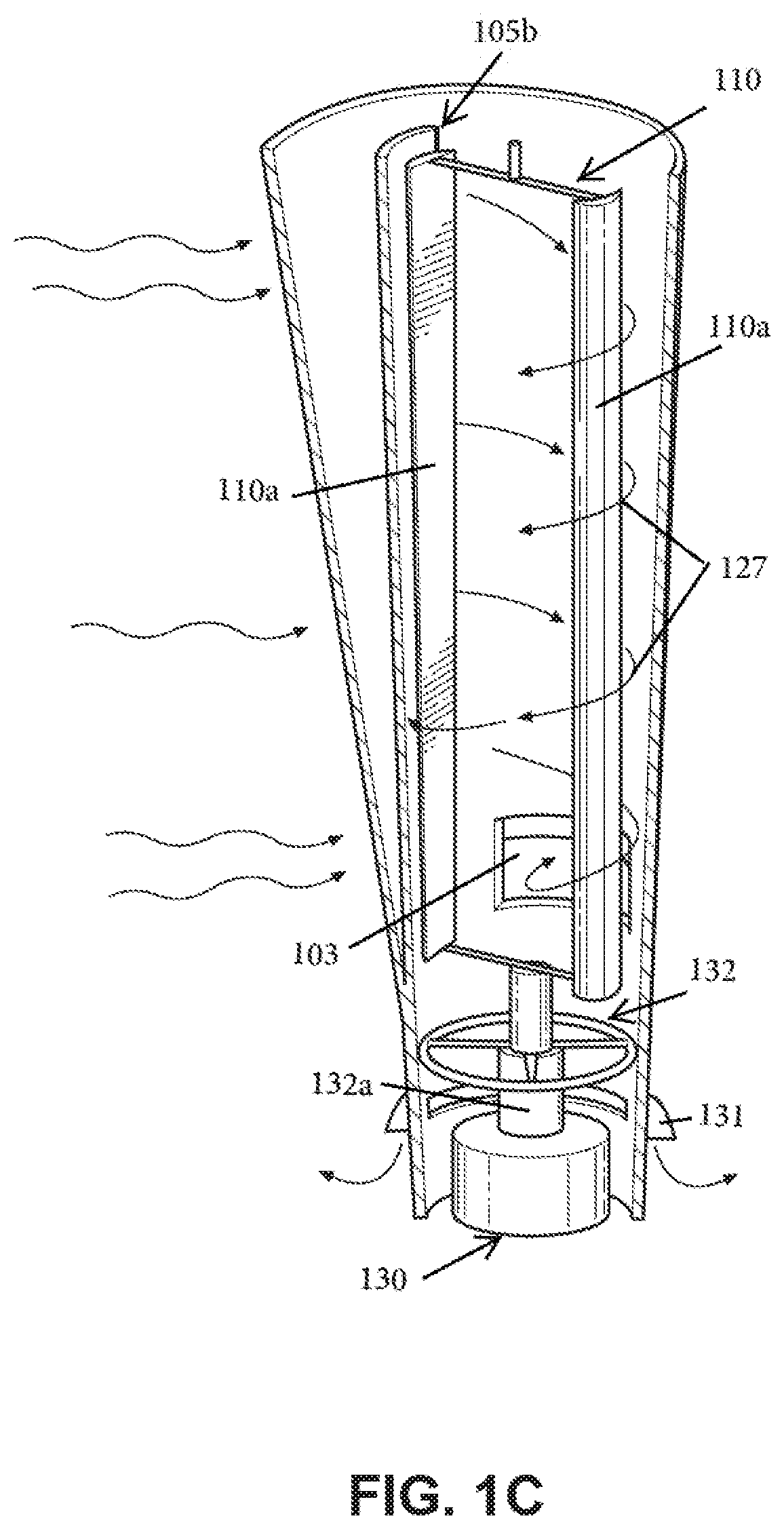
[0028]In an aspect, a wind harvesting assembly for a wind turbine is provided, the wind harvesting assembly comprising: a Venturi tube having: a hollow interior having a first air pressure; an open top end having a first diameter; an open bottom end having the first diameter; a tube length spanning between the open top end and the open bottom end; and a constricted section located above the bottom end, the constricted section being adapted to increase a velocity of air passing through the Venturi tube and cause an expulsion of air out of the Venturi tube by having a second diameter smaller than the first diameter; a plurality of vertical wind turbine blades arranged around the Venturi tube, wherein each vertical blade of the plurality of vertical wind turbine blades is associated with a magnet, such that a rotation of the vertical blade causes a rotation of the magnet; and wherein each vertical blade of the plurality of vertical wind turbine blades has: a blade top end; a blade bottom end; and a blade length spanning between the blade top end and the blade bottom end, the length being the same as the tube length, and being aligned with the tube length, such that the blade top end is aligned with the open top end, and the blade bottom end is aligned with the open bottom end; wherein the first air pressure within the hollow interior is lower than a second air pressure outside of the wind harvesting assembly, resulting in a pressure differential that causes a suction effect of a first portion of air into the open top end from wind passing over the wind harvesting assembly, such that the first portion of air becomes the air passing through the Venturi tube; wherein the rotation of the plurality of vertical wind turbine blades is caused when a second portion of air is ingested into the wind turbine and forced to become a vortex having a higher speed than the ingested air, the vortex being a spiral air stream traveling towards the open bottom end; and wherein the open bottom end is adapted to facilitate the expulsion of air out of the Venturi tube. Thus, an advantage is that a lowest pressure zone (“lowest pressure,” or “lowest pressure zone”) may be maintained near the exit points of the air from the wind turbine, which may help to maintain stability of the vortex of air in the wind turbine. Another advantage is that the lowest pressure zone may help the wind turbine to begin turning while in low wind speed environments. Another advantage is that the blade assembly may be provided in smaller sizes than other similar wind turbines, such that the blade rotation can be started with a lower wind speed, and also reduce cost and materials of the wind turbine construction. Another advantage is that the Venturi tube may help to increase wind speeds traveling through the wind turbine and more efficiently harvest the power from the air, and more quickly expel air out of the wind turbine, which may also help to maintain stability of the wind vortex within the wind turbine.
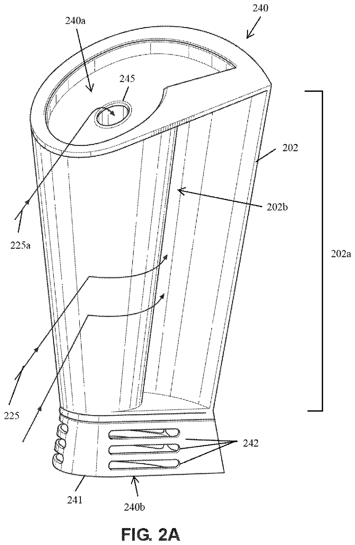
[0029]In another aspect, a wind turbine comprising a wind harvesting assembly and a housing is provided, the wind harvesting assembly being encased in a hollow housing interior of the housing, the housing having: a top housing end; a base at a bottom housing end, the base having a hollow base interior, a top base end, a bottom base end, and means for a first expulsion of air out of the wind turbine; an intake opening spanning between the top housing end and the bottom housing end; a Venturi tube having: a hollow interior having a first air pressure; an open top end having a first diameter, the open top end being located at the top housing end; an open bottom end having the first diameter, the open bottom end being located at the top base end; a tube length spanning between the open top end and the open bottom end; and a constricted section located above the bottom end, the constricted section being adapted to increase a velocity of air passing through the Venturi tube cause a second expulsion of air out of the Venturi

Problems solved by technology

Moreover, this Summary is not intended for use as an aid

Method used


Image

  • Venturi vortex and flow facilitating turbine
  • Venturi vortex and flow facilitating turbine
  • Venturi vortex and flow facilitating turbine

Examples


Embodiment Construction

[0040]What follows is a description of various aspects, embodiments and / or examples in which the invention may be practiced. Reference will be made to the attached drawings, and the information included in the drawings is part of this detailed description. The aspects, embodiments and / or examples described herein are presented for exemplification purposes, and not for limitation purposes. It should be understood that structural and / or logical modifications could be made by someone of ordinary skills in the art without departing from the scope of the invention. Therefore, the scope of the invention is defined by the accompanying claims and their equivalents.

[0041]It should be understood that, for clarity of the drawings and of the specification, some or all details about some structural components or steps that are known in the art are not shown or described if they are not necessary for the invention to be understood by one of ordinary skills in the art.

[0042]For the following descr...


PUM


Abstract

A wind harvesting assembly for a wind turbine, having: a Venturi tube having a hollow interior having a first air pressure; an open top end having a first diameter; an open bottom end having the first diameter; a tube length spanning between the open top end and the open bottom end; and a constricted section located above the bottom end, the constricted section adapted to increase a velocity of air passing through by having a second diameter smaller than the first diameter; a plurality of vertical wind turbine blades arranged around the Venturi tube, wherein each vertical blade of the plurality of vertical wind turbine blades is associated with permanent magnets.

Description

CROSS-REFERENCE TO RELATED APPLICATIONS[0001]This application relates to U.S. Non-Provisional application Ser. No. 14 / 822,728, filed Aug. 10, 2015, now U.S. Pat. No. 9,371,818, which is hereby incorporated by reference, to the extent that it is not conflicting with the present application.BACKGROUND OF INVENTION1. Field of the Invention[0002]The invention relates generally to wind turbines and more particularly to methods, systems, and apparatuses for increasing the efficiency of wind turbines by taking advantage of the Venturi effect.2. Description of the Related Art[0003]Horizontal Wind Turbines (HWTs) and Vertical Axis Wind Turbines (VAWTs) used for harnessing wind energy have several drawbacks, which include a large amount of space needed for power generation, damage to the turbine blades by bird strikes, potential damage to other structures or harm to a population if a blade is ejected from the turbine or if ice buildup on the blades are thrown, as well as other problems. A cyc...

Claims


Application Information

Patent Timeline
IPC IPC(8): F03D3/04F03D3/00F03D3/06
CPCF05B2240/131F03D3/0427F05B2240/211F05B2220/7068F05B2240/132F05B2240/133F03D3/005F03D3/062F05B2240/214F03D9/39Y02E10/728Y02E10/74
Inventor MONTO, MARK
Owner MONTO MARK
Why Eureka
Try Eureka