Cooling circuit flow path for a turbine section airfoil

a cooling circuit and turbine section technology, applied in the direction of machines/engines, sustainable transportation, mechanical equipment, etc., can solve the problems of reducing the efficiency of the engine, the effectiveness of the airfoil, and the leading edge heat load of the high-pressure turbine blade, so as to achieve efficient utilization of the cooling airflow

Active Publication Date: 2014-06-24
RTX CORP
View PDF17 Cites 26 Cited by
  • Summary
  • Abstract
  • Description
  • Claims
  • Application Information

AI Technical Summary

Benefits of technology

[0008]The cooled airfoil according to the present invention includes a forward cavity defined by at least one impingement rib. The impingement rib separates the forward cavity from a leading edge cavity defined at least partially by an outer airfoil wall surface often referred to as a “peanut” cavity. The impingement rib includes a multiple of openings which supply a cooling airflow from a cooling circuit flow path toward the leading edge. The openings operate as nozzles to increase the cooling airflow velocity and expand the cooling airflow to further increase the thermal transfer qualities thereof. The cooling airflow is expelled from the leading edge cavity through leading edge “showerhead” holes as well as, in some locations, “gill” holes.
[0009]The multiple of openings are offset in the impingement rib in a direction opposite the outer airfoil wall which includes the “gill” holes. Offsetting the multiple of openings opposite an outer airfoil wall which includes the “gill” holes focuses the cooling airflow across turbulators to increase the cooling airflow dwell time adjacent a higher temperature area of the airfoil wall to increase the thermal transfer therefrom. That is, a lesser quantity of “gill” holes are required yet increased thermal transfer from the higher temperature areas is provided. This more effectively utilizes a minimal cooling airflow volume to reduce the effect on engine efficiency.
[0011]The present invention therefore provides a combustion section cooling circuit flow path for a component which receives a cooling airflow therethrough as an external surface thereof is exposed to a high temperature combustion core gas flow while efficiently utilizing the cooling airflow.

Problems solved by technology

High pressure turbine vanes and blades typically have relatively high heat loads at the leading edges.
“Gill” holes are also often utilized in specific high temperature areas to provide targeted cooling on these particular areas, however, the diversion of significant cooling airflow may decrease the efficiency of the engine.
Furthermore, “gill” holes located in some airfoil areas may undesirably decrease the airfoil effectiveness thus further decreasing engine efficiency.

Method used


Image

  • Cooling circuit flow path for a turbine section airfoil
  • Cooling circuit flow path for a turbine section airfoil
  • Cooling circuit flow path for a turbine section airfoil

Examples


Embodiment Construction

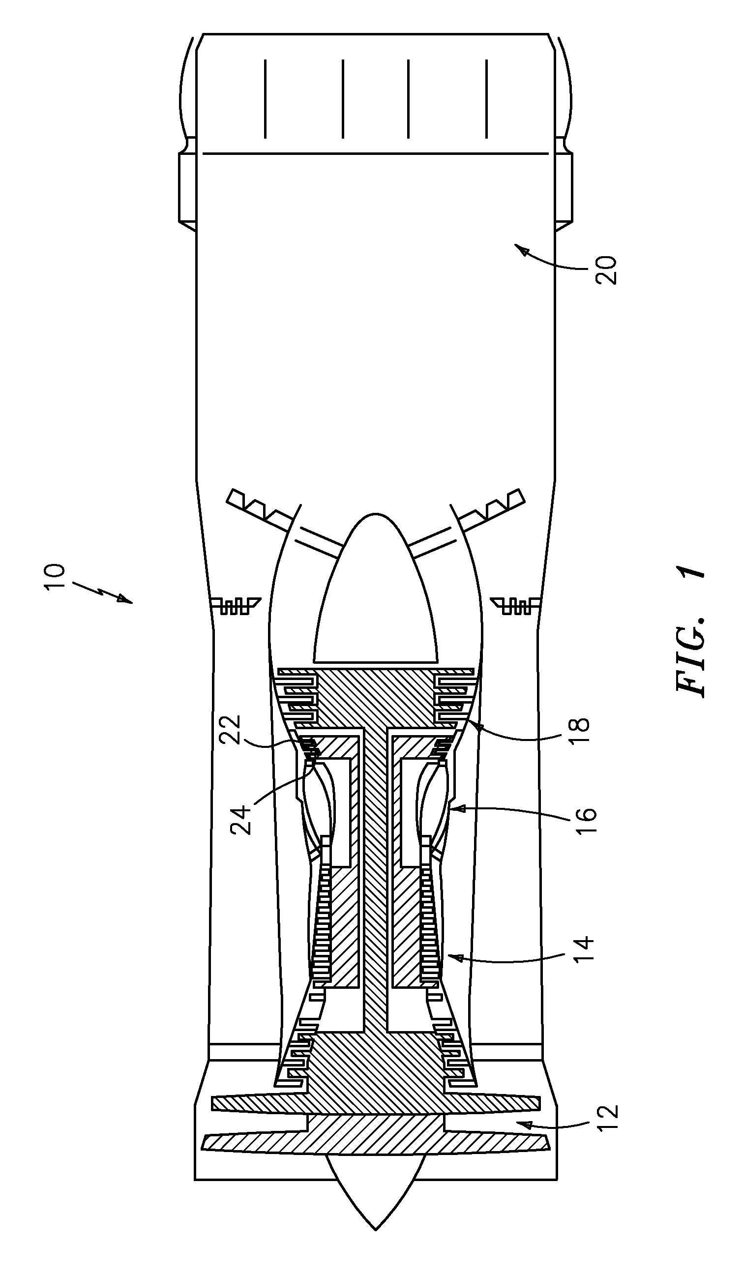
[0023]FIG. 1 schematically illustrates a gas turbine engine 10 which generally includes a fan section 12, a compressor section 14, a combustor section 16, a turbine section 18, and a nozzle section 20. Within and aft of the combustor 16, engine components are typically cooled due to intense temperatures of the combustion core gases.

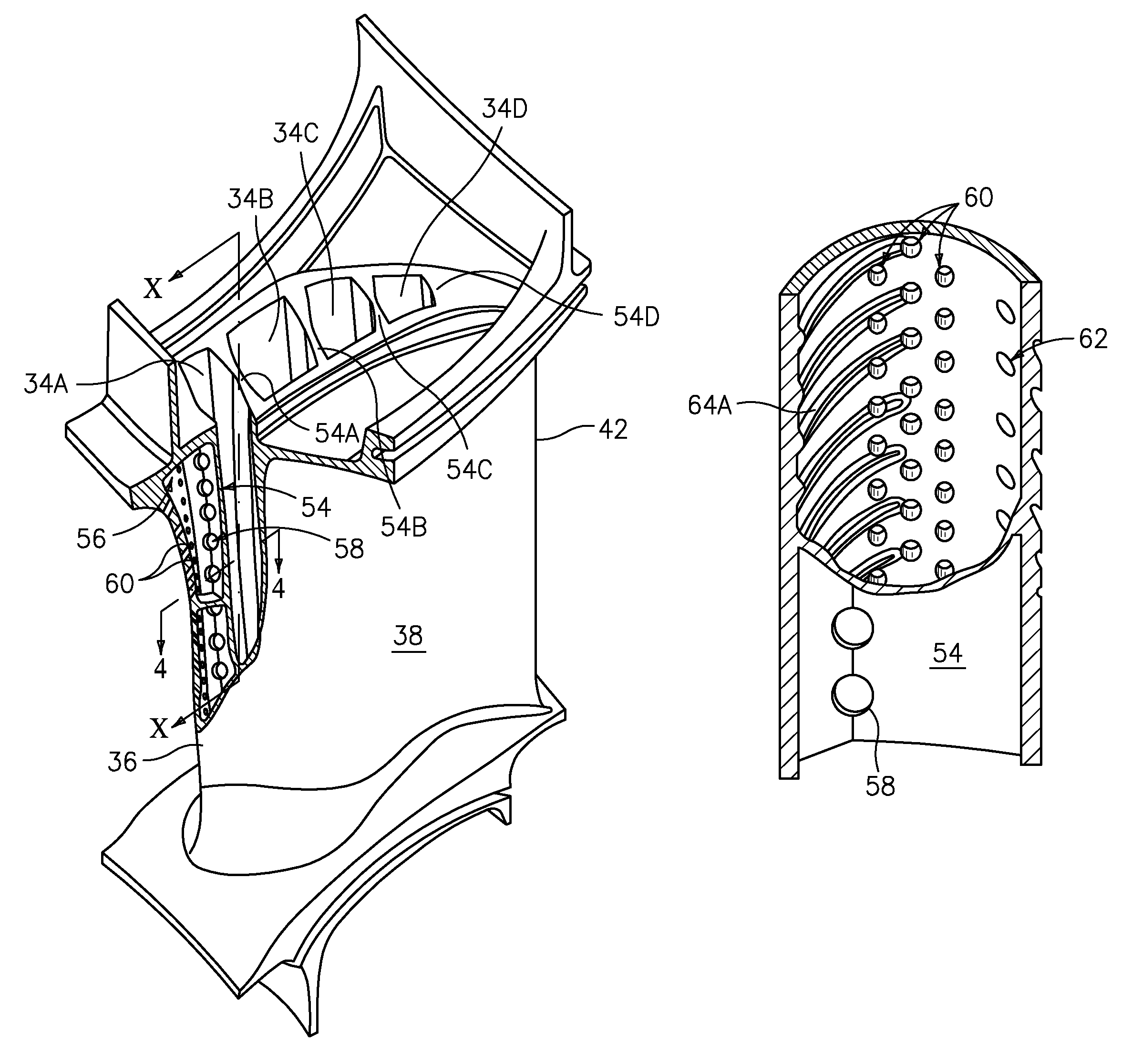
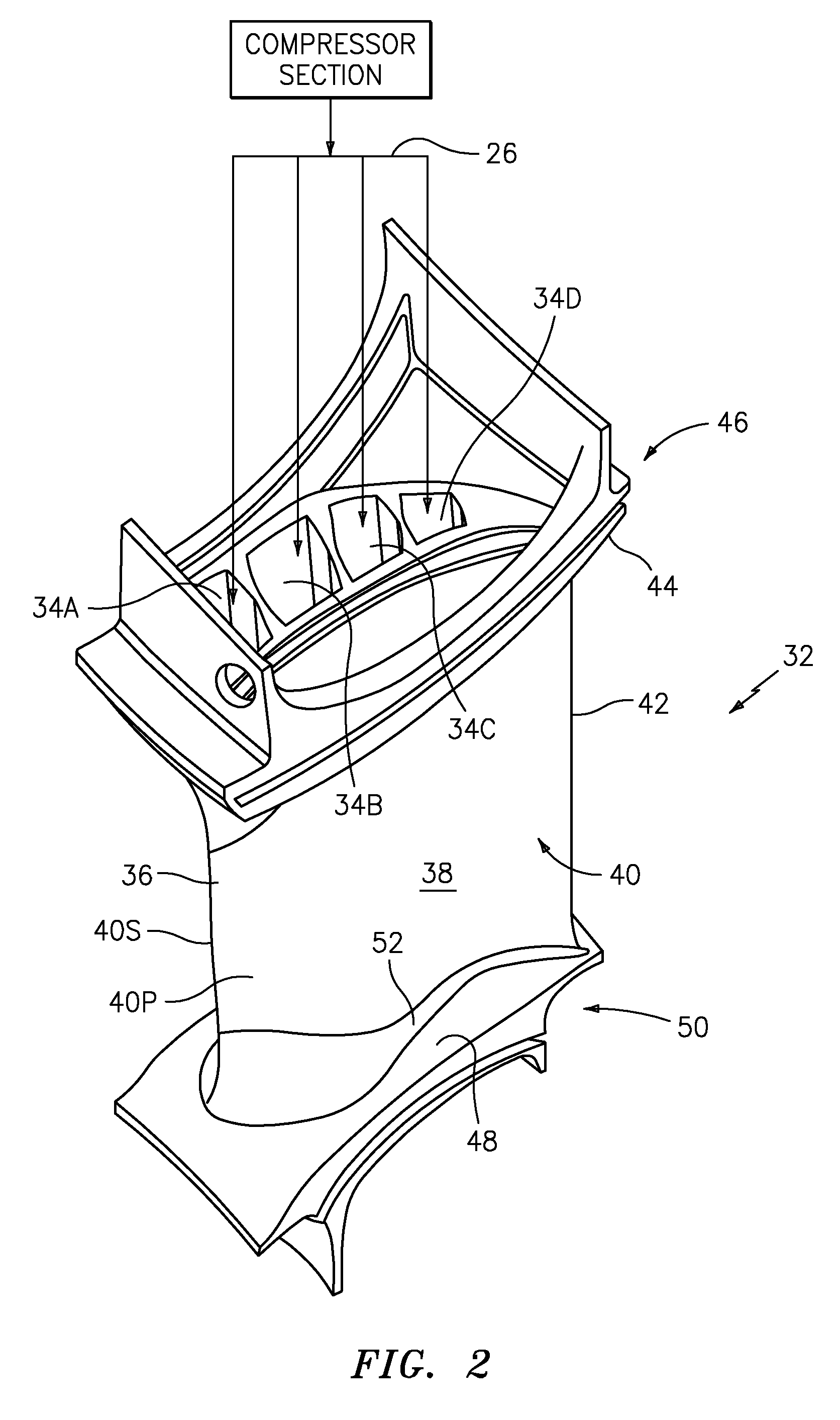
[0024]Initial turbine rotor stages 22 and turbine stator vane stages 24 within the turbine section 18, for example, are cooled with a cooling airflow typically sourced with a bleed airflow from the compressor section 14 at a pressure higher and temperature lower than the core gas within the turbine section 18. The cooling airflow passes through at least one cooling circuit flow paths 26 (FIG. 2) to transfer thermal energy from the component to the cooling airflow. Each cooling circuit flow path 26 may be disposed in any component that requires cooling, and in most cases the component receive cooling airflow therethrough as the external surface thereof is ...


PUM


Abstract

A cooled airfoil includes an impingement rib having a multiple of openings which supply a cooling airflow from a cooling circuit flow path toward an airfoil leading edge. The multiple of openings are offset in the impingement rib opposite an outer airfoil wall which includes gill holes. Offsetting the multiple of openings opposite an outer airfoil wall which includes the gill holes focuses the cooling airflow across turbulators to increase the cooling airflow dwell time to increase the thermal transfer therefrom in higher temperature airfoil areas.

Description

[0001]This invention was made with government support under Contract No.: N00019-02-C-3003 awarded by the Department of the Air Force. The government therefore has certain rights in this invention.BACKGROUND OF THE INVENTION[0002]The present invention relates to a gas turbine engine, and more particularly to a combustion section cooling circuit flow path for a component which receives a cooling airflow therethrough as the external surface thereof are exposed to combustion exhaust gases.[0003]A gas turbine engine includes a compressor section that compresses air then channels the compressed air to a combustor section wherein the compressed airflow is mixed with fuel and ignited to generate high temperature combustion gases. The combustion core gases flow downstream through a turbine section which extracts energy therefrom for powering the compressor section and produce additional output power for driving a fan section.[0004]A turbine stage includes a row of turbine rotor blades secur...

Claims


Application Information

Patent Timeline
Patent Type & Authority Patents(United States)
IPC IPC(8): F01D5/18
CPCF01D5/186F01D5/188F05D2240/121F05D2240/303F05D2260/22141Y02T50/60
Inventor PROPHETER-HINCKLEY, TRACY A.CHON, YOUNG H.BRIDGES, JR., JOSEPH W.
Owner RTX CORP
Why Eureka
Try Eureka