Piezoelectric-Based Multiple Impact Sensors and Their Electronic Circuitry
a technology of electronic circuitry and sensors, applied in the field of piezoelectric-based sensors, can solve the problems of reducing the efficiency of thermal battery manufacturing, so as to reduce the size of the energy harvesting device and its components, and efficient harvesting of electrical energy
- Summary
- Abstract
- Description
- Claims
- Application Information
AI Technical Summary
Benefits of technology
Problems solved by technology
Method used
Image
Examples
first embodiment
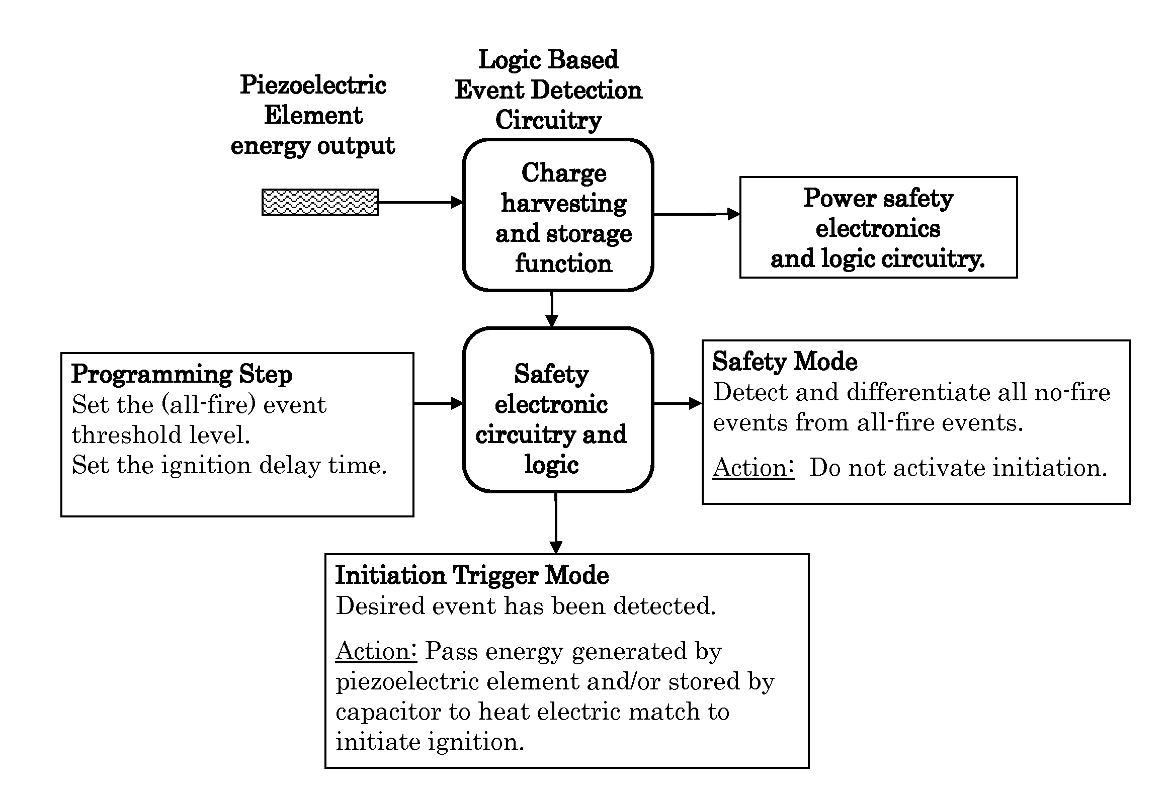
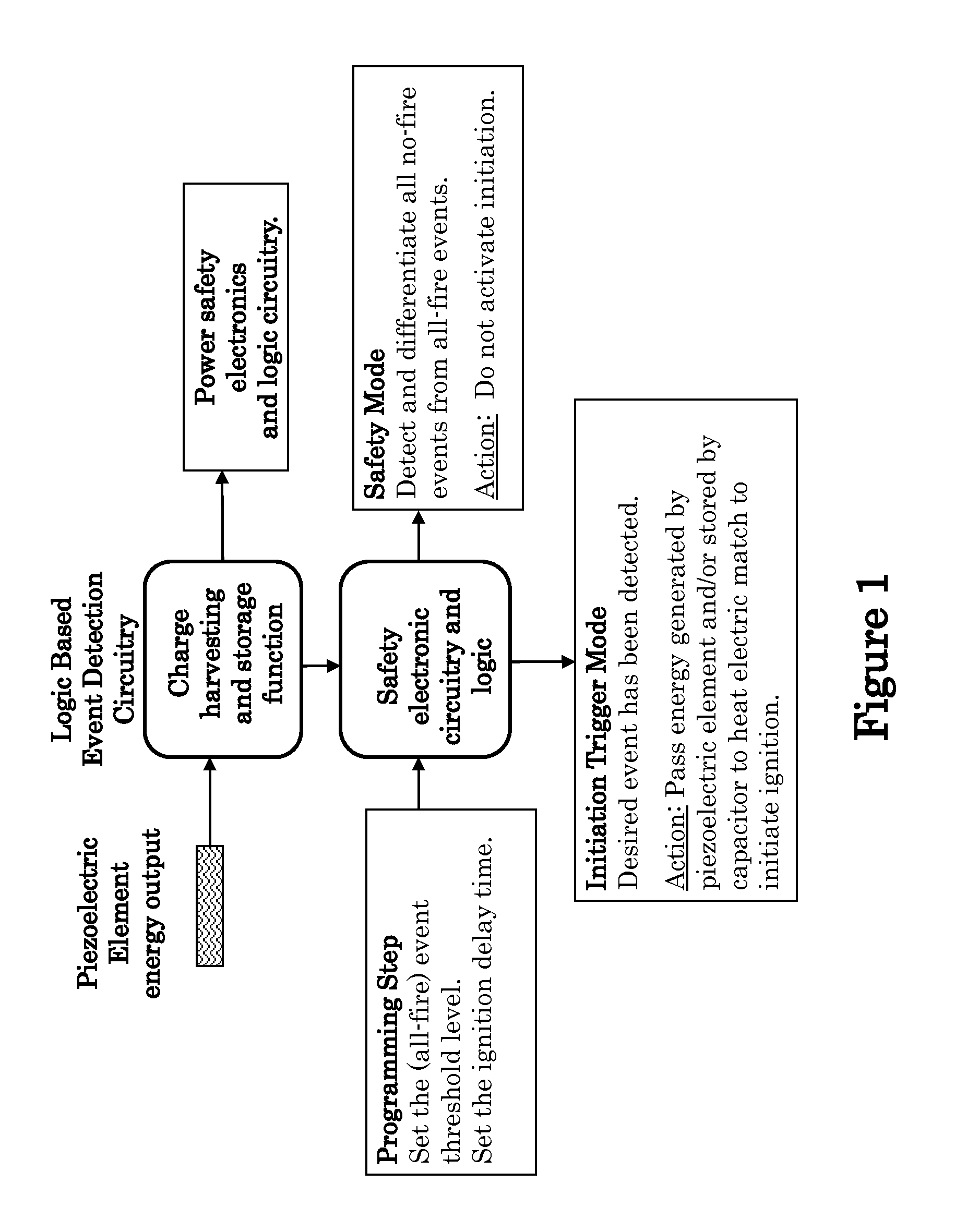
[0109]The block diagram of a programmable electrically initiated inertial igniter is shown in FIG. 1. In this embodiment, an appropriately sized piezoelectric element (different options of which are described later in this disclosure) is used, which responds to the axial accelerations and / or decelerations of the munitions or the like, to which it is affixed via a thermal battery or the like. In response to the aforementioned axial accelerations and / or decelerations of the piezoelectric element, a charge is generated on the piezoelectric element due to the resulting forces acting on the piezoelectric element due to its mass and the mass of other elements acting on the piezoelectric element (if any). As a result, the sign of the corresponding voltage on the piezoelectric element would readily indicate the direction of the axial acceleration that is applied to the munitions due to the firing or accidental dropping or other similar no-fire conditions.
[0110]However, the detection of the ...
second embodiment
[0176]In the passive initiators for pyrotechnic material or the like with the above safety and low power characteristics, when the noise due to sources such as electromagenetic interference (EMI) and electromagnetic pulse (EMP) and other internal and external sources is either very low or has been taken care of using appropriate shielding and filtering, then a Silicon Controlled Rectifier (SCR) may be used in place of the two transistors Q2 and Q3 in the embodiment of FIG. 14 as shown in the circuitry of FIG. 16. The SCR is a switch driven by gate current and would stay enabled while a current is being passed through it.
[0177]Then as was described for the embodiment of FIG. 15, by appropriately selecting the component parameters of the “output voltage threshold detection and switching element” portion of the circuitry shown in FIG. 16, when the voltage at the OUTPUT of the safety and all-fire detection circuitry (FIGS. 13 and 16) reaches the prescribed all-fire threshold, the N-MOS ...
third embodiment
[0274]the piezoelectric based multiple shock loading detection and shock load profile measuring sensor is intended to dissipate the piezoelectric element output energy in a relatively small frequency range (window) for the purpose of significantly reducing the sensor output caused by the dominant natural mode(s) of vibration of the platform to which the present sensor is attached as was described above.
[0275]The schematic of this third embodiment of the piezoelectric based multiple shock loading detection and shock load profile measuring sensor is shown in FIG. 40. This circuitry uses the basic safety and all-fire detection circuitry shown in FIG. 13 and functions as was described for the circuitry and is considered to be passive since it does not require any external source of power or batteries or other similar sources of chemical or externally charged power sources for its operation.
[0276]In the embodiment of FIG. 40, to significantly dissipate the piezoelectric element output en...
PUM
| Property | Measurement | Unit |
|---|---|---|
| volumes | aaaaa | aaaaa |
| volumes | aaaaa | aaaaa |
| ITM time constant | aaaaa | aaaaa |
Abstract
Description
Claims
Application Information
 - R&D
- Intellectual Property
- Life Sciences
- Materials
- Tech Scout
- Unparalleled Data Quality
- Higher Quality Content
- 60% Fewer Hallucinations
Browse by: Latest US Patents, China's latest patents, Technical Efficacy Thesaurus, Application Domain, Technology Topic, Popular Technical Reports.
© 2025 PatSnap. All rights reserved.Legal|Privacy policy|Modern Slavery Act Transparency Statement|Sitemap|About US| Contact US: help@patsnap.com


