
Multi-directional high-efficiency piezoelectric energy transducer

a piezoelectric energy transducer, multi-directional technology, applied in the direction of piezoelectric/electrostriction/magnetostriction machines, electrical transducers, electrical apparatus, etc., can solve the problems of high cost, time-consuming, and inability to replace or maintain such a large number of batteries, and achieve a wide range of working bandwidth, strong intrinsic nonlinearity, and wide bandwidth

Inactive Publication Date: 2015-12-10
YANG ZHENGBAO +1
View PDF3 Cites 10 Cited by
  • Summary
  • Abstract
  • Description
  • Claims
  • Application Information

AI Technical Summary

Benefits of technology

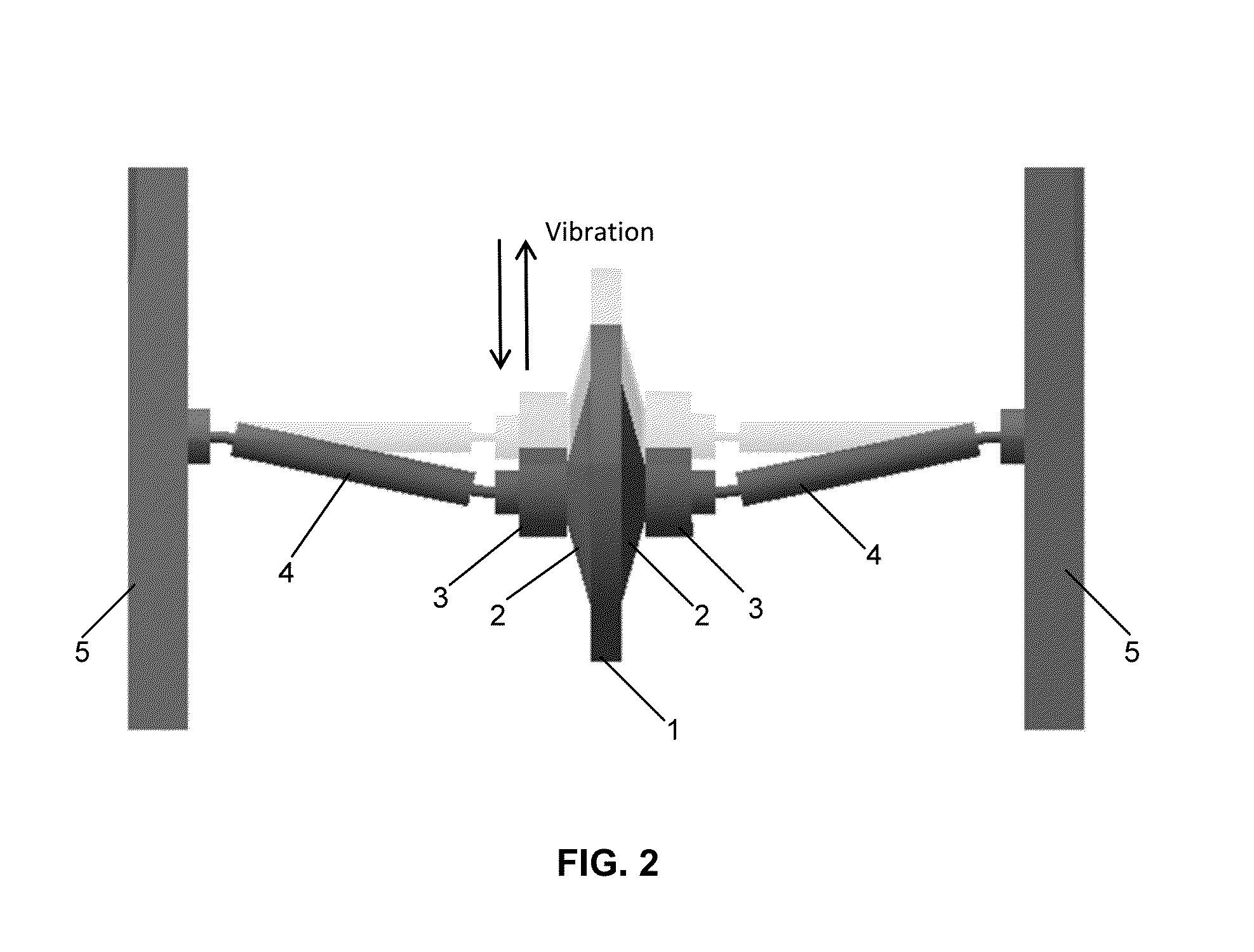
The invention is a device that can efficiently harvest low-frequency, weak vibration energy. It uses a special piezoelectric component that works in a compressive mode, which is over 10 times stronger than other modes. The device also has bow-shaped metal plates that protect the piezoelectric element from failure to a certain extent. Additionally, a nonlinear mechanism can be introduced into the system to get a broader bandwidth. The structure itself shows strong intrinsic nonlinearity, and can be further enhanced by adding axial preload or a magnetic field. The elastic beams in the device change the vibration direction to axial direction and amplify the induced force. The accumulated amplification mechanism and the property of low resonance frequency of beams are synthesized in this invention, making it able to efficiently harvest low-frequency, weak vibration energy.

Problems solved by technology

Those electronics are usually small, compact and need to have a long lasting power source.
For instance, the forest fire monitoring system that consists of a very large number of sensors distributed over a large area, replacement or maintenance of such a large number of batteries is extremely pricy and time-consuming.
This type of system has relatively low resonance frequency but poor energy output.
Due to its weak mechanical strength, these kind of energy harvesters operating in bending mode can easily develop line cracks in piezoelectric materials.
Besides, the resonance frequency of cymbal configurations is far higher than that of excitation sources, which is detrimental to the efficiency of energy harvesters.
Typical energy harvesters, like bimorph cantilever, cymbal or their derived structures suffer from significant attenuation of power response if vibration sources do not vibrate in the pre-designed transverse direction.
While vibration sources like human motion, machine vibration are not always kept in a fixed direction.

Method used


Image

  • Multi-directional high-efficiency piezoelectric energy transducer
  • Multi-directional high-efficiency piezoelectric energy transducer
  • Multi-directional high-efficiency piezoelectric energy transducer

Examples


Embodiment Construction

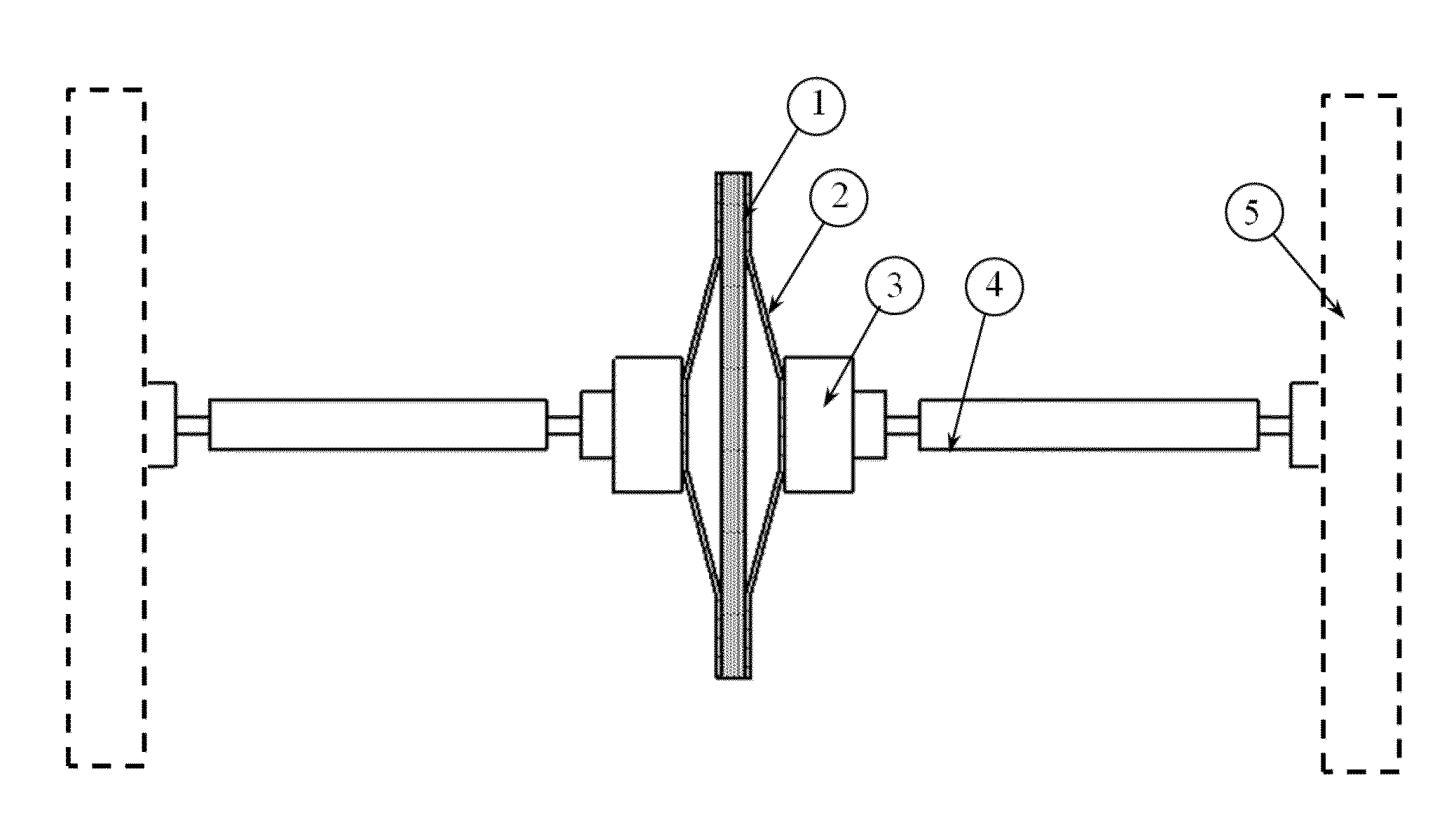
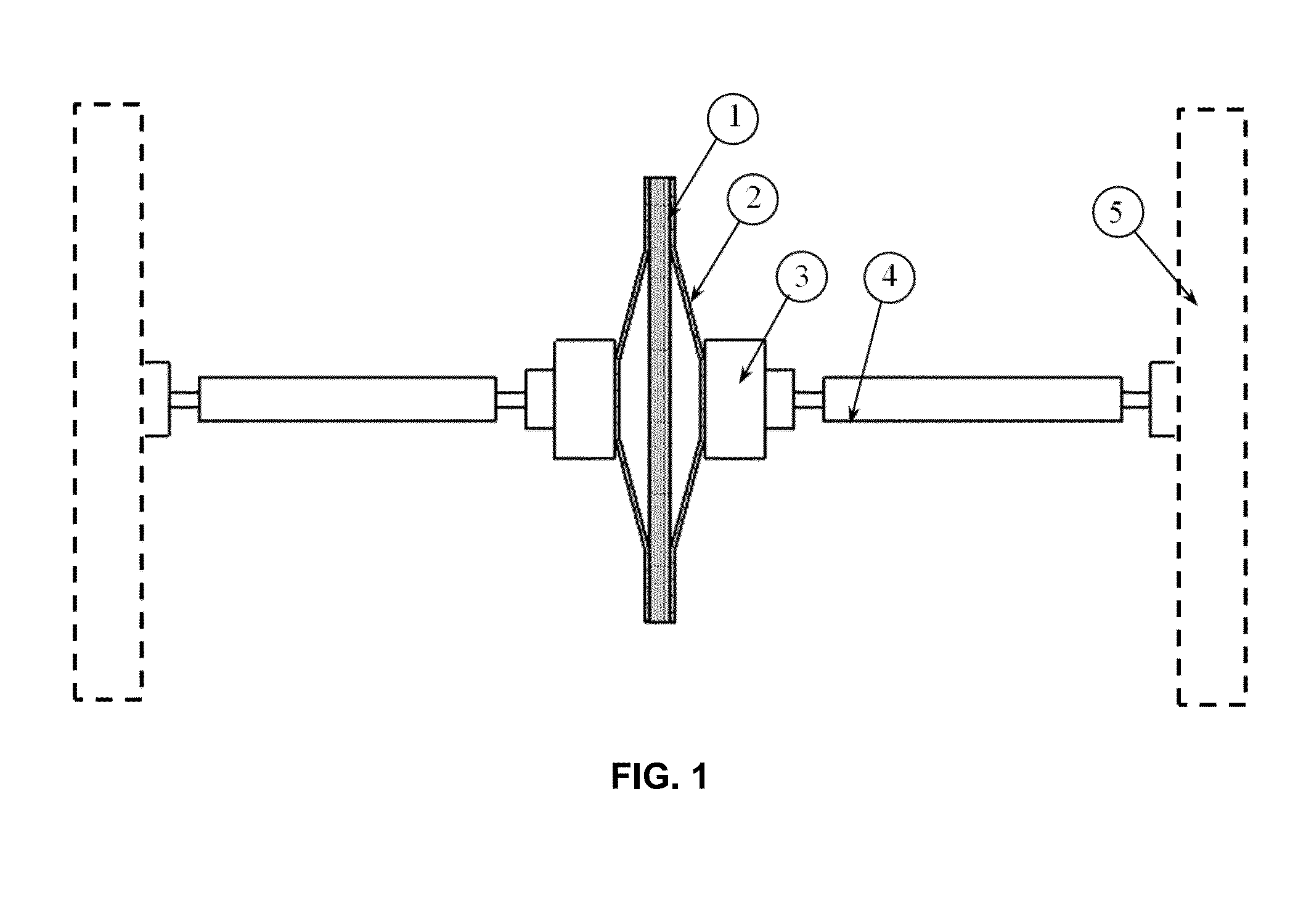
[0029]FIG. 1 shows a functional block diagram of the multi-directional high-efficiency energy harvesting device in accordance with the present invention. The device includes a center flextensional component comprising of piezoelectric materials 1 and a pair of bow-shaped plates 2, two proof mass 3, two elastic beams 4 and a base 5. The base 5 is used to fix the device and it can be anything in practice, like a bridge, an airplane, a vehicle or a pacemaker, etc.

[0030]The employed piezoelectric material 1 can be piezoceramics like PZT, PVDF, quartz, single crystal materials, like PMN-PT or others that have high piezoelectric constants and high electromechanical coupling constants or magnetostrictive materials. The configurations can be one-layer unimorph, two-layer bimorph or multi-layer stack. It can work at different mode piezoelectric effects (d31, d33, d15 and so on).

[0031]Bow-shaped metal plates 2 serve as mechanical transformers for transforming and amplifying a portion of the i...


PUM


Abstract

A piezoelectric transducer for harvesting ambient vibration energy is made up of two elastic beams poled for series operation, a center flextensional component and two proof masses. The center flextensional component serves as the energy harvesting part as well as vibration harvesting inertial mass. The energy harvester is capable of harvesting multi-directional low-frequency vibration energy efficiently. It can be applied in implantable devices, wearable electronics and wireless sensor networks.

Description

RELATED APPLICATION[0001]The present invention was first described in U.S. Provisional Patent No. 61 / 837,727 filed on Jun. 21, 2013.FIELD OF THE INVENTION[0002]The invention relates generally to energy harvesting from ambient vibration.DESCRIPTION OF RELATED ART[0003]Communication devices, sensor networks, wearable electronics, implantable devices, etc. play increasingly important role in modern life. Those electronics are usually small, compact and need to have a long lasting power source. For instance, the forest fire monitoring system that consists of a very large number of sensors distributed over a large area, replacement or maintenance of such a large number of batteries is extremely pricy and time-consuming. In response to the urgent need to develop lightweight power supplies having high energy density and long lifetime, the present invention provides a self-powered solution.[0004]The available self-powered solutions are based on utilizing various types of external sources su...

Claims


Application Information

Patent Timeline
IPC IPC(8): H04R17/00
CPCH04R17/00H02N2/186H10N30/30
Inventor YANG, ZHENGBAOZU, JEAN W.
Owner YANG ZHENGBAO
Learn More