

Distributedly modulated capacitors for non-reciprocal components
- Summary
- Abstract
- Description
- Claims
- Application Information
AI Technical Summary
Benefits of technology
Problems solved by technology
Method used
Image

Examples
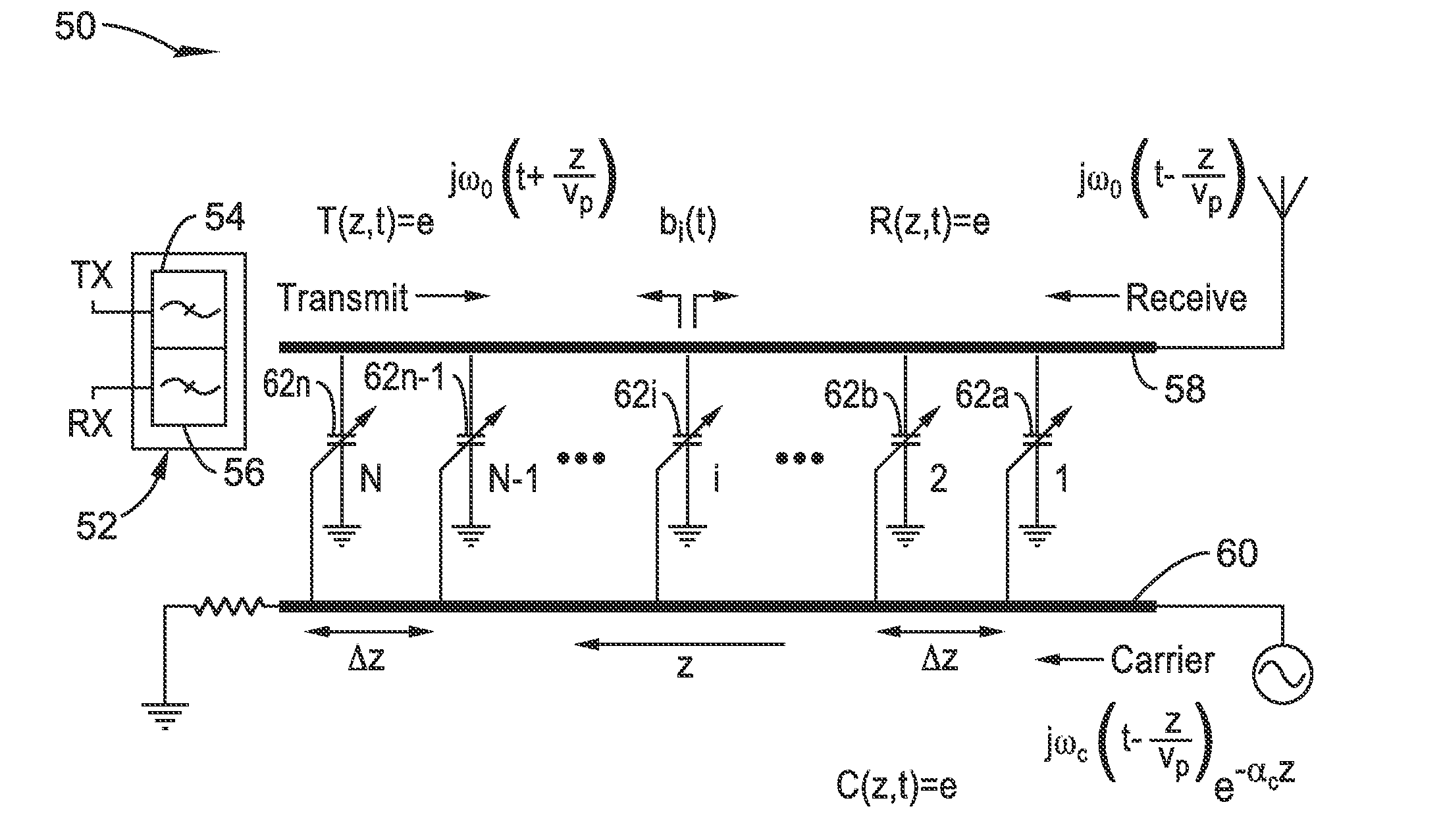
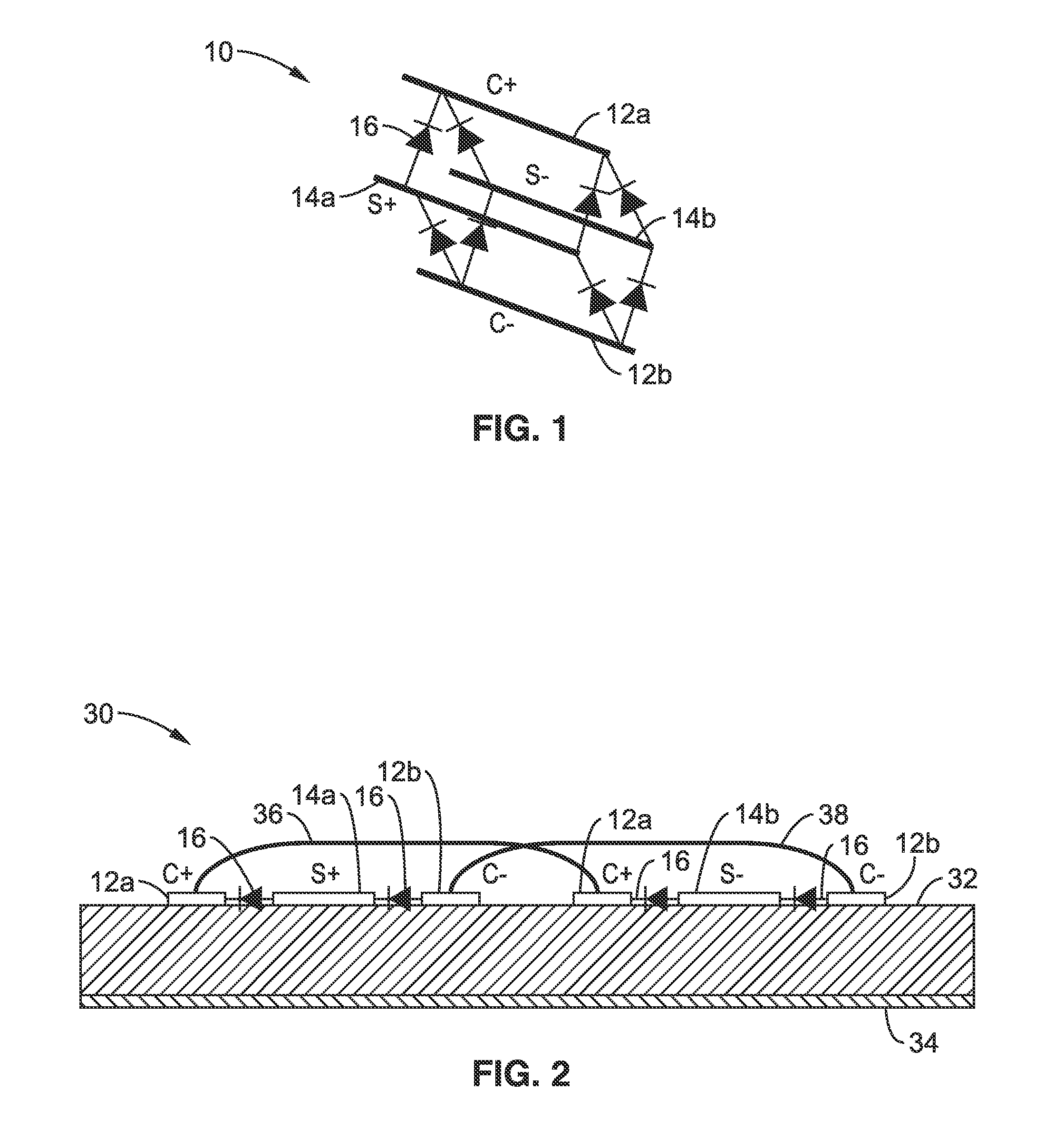
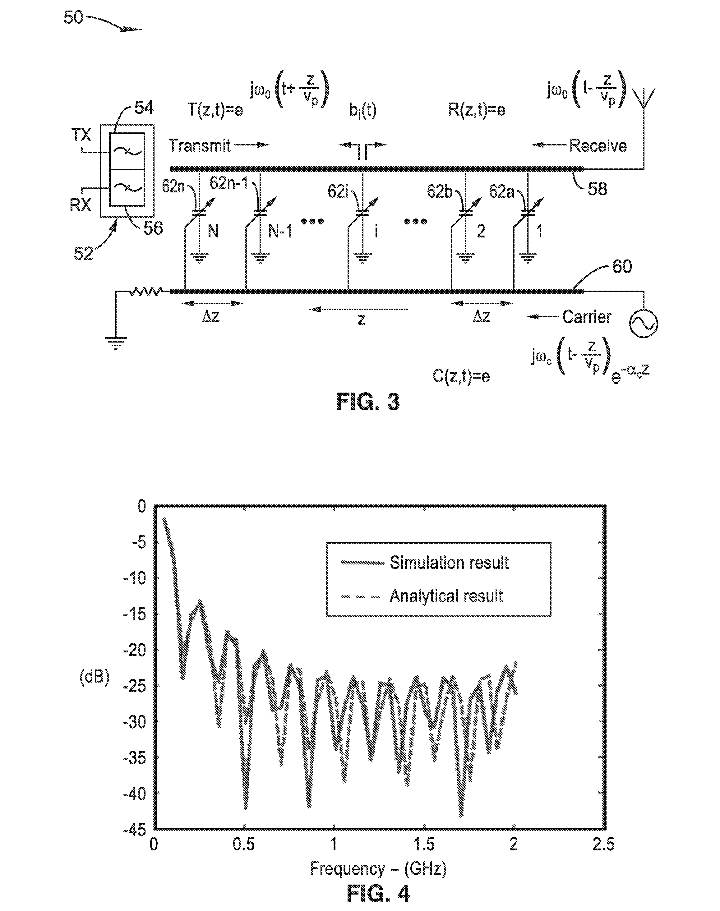
embodiment 10
[0028]In FIG. 1 a schematic illustrates an embodiment 10 of such a structure with carrier lines C+ 12a, C−12b, signal lines S+ 14a, and S−14b, and varactor diodes 16 interconnecting between each of the signal lines for each unit cell along these lines. The cathode sides of the varactor diodes are oriented toward C+ 12a and S+ 14a respectively. The double balanced configuration as depicted allows the cancellation of the capacitance modulation caused by the signal voltage and the construction of the capacitance modulation caused by the carrier voltage. This is to achieve the transmission line capacitance modulation solely by the carrier while maintaining the linearity of the signal in transmitting and receiving.
embodiment 30
[0029]In FIG. 2 is seen illustrated an embodiment 30 upon a substrate 32 with ground plane 34. In at least one preferred embodiment, this substrate comprises a microstrip line realization (shown here in cross-section). One can see that C+ 12a, and C−12b lines are duplicated on each side of lines S+ 14a, and S−14b which are interconnected between each unit cell with varactor diodes 16, as was seen in FIG. 1. Bonding wires 36, 38, are seen interconnecting the two C+ lines 12a, and the two C− lines 12b. Alternatively, it will be appreciated that the S lines could be duplicated and placed on each side of the C lines. The theory behind DMC operation, such as exemplified but not limited to the embodiments shown in FIG. 1 and FIG. 2 are discussed below.
[0030]Transmission Line Solutions with Time-Varying Capacitances.
[0031]Transmission lines whose reactance is time-varying are known to have interesting properties. One of the classical applications is the traveling wave parametric amplifiers...
PUM
 Abstract
Description
Claims
Application Information