
LED-based luminaire utilizing optical feedback color and intensity control scheme

a technology of optical feedback and luminaires, applied in the direction of electric controllers, instruments, ignition automatic control, etc., can solve the problems that conventional luminaires based on solid state sources do not maintain desired intensity and/or color during their lifetim

Inactive Publication Date: 2006-01-12
HONEYWELL INT INC
View PDF19 Cites 129 Cited by
  • Summary
  • Abstract
  • Description
  • Claims
  • Application Information

AI Technical Summary

Benefits of technology

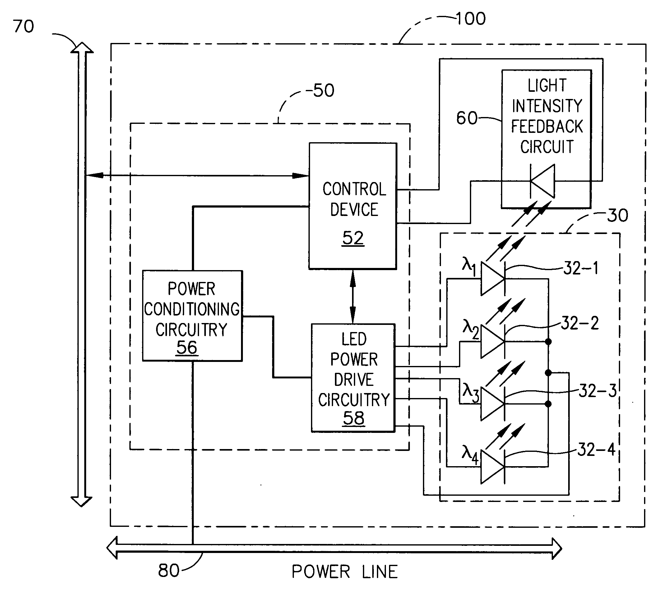
[0008] According to an exemplary embodiment, the controller may receive the desired intensity / color setting from an input device, or a data bus connected to an input device. Such an embodiment allows the luminaire output to be maintained at an adjustable setting.
[0010] Thus, the control scheme according to exemplary embodiments of the present invention may be used to provide consistent, uniform color / intensity, despite LED output changes caused by manufacturing variations, temperature fluctuations, and / or lumen degradation over the life of the luminaire.

Problems solved by technology

Consequently, conventional luminaires based on solid state sources do not maintain desired intensity and / or color during their lifetime.

Method used


Image

  • LED-based luminaire utilizing optical feedback color and intensity control scheme
  • LED-based luminaire utilizing optical feedback color and intensity control scheme
  • LED-based luminaire utilizing optical feedback color and intensity control scheme

Examples


Embodiment Construction

[0014] According to an exemplary embodiment, the present invention is directed to a luminaire with a light-emitting diode (LED)-based light source, which receives feedback from an optical sensor to maintain the luminaire's output at a desired level. In an exemplary embodiment, the luminaire uses this feedback to adjust the current delivered to the LED(s) in the luminaire to ensure that the output retains a desired intensity and / or color despite temperature variations and lumen depreciation of the LED(s).

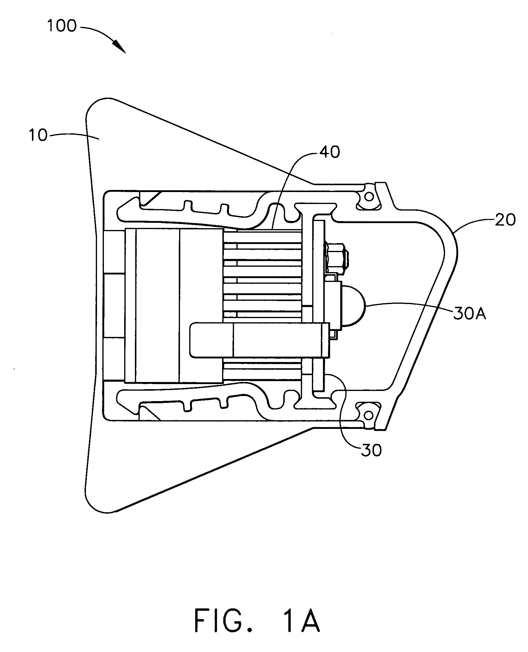
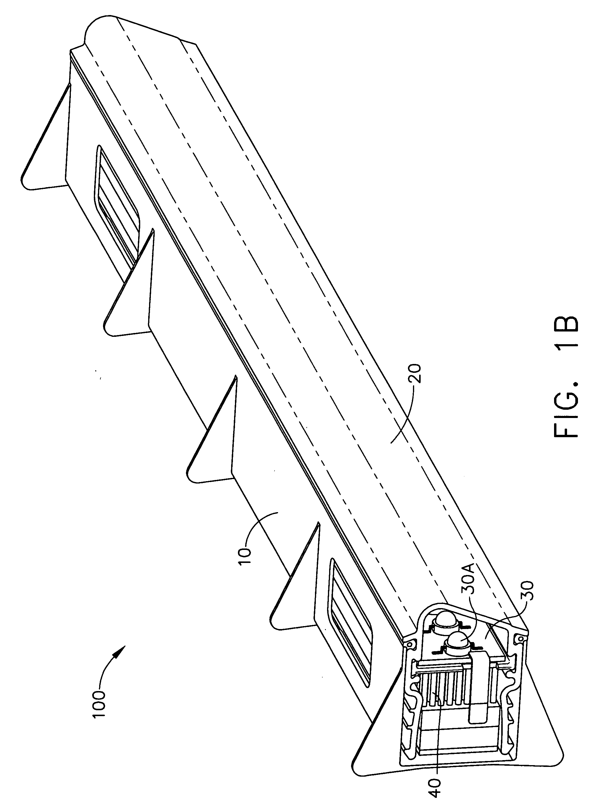
[0015] Various aspects of these components are illustrated in FIGS. 1A-1C, in accordance with an exemplary embodiment. In particular, FIG. 1A illustrates a cross-sectional view of a luminaire 100, according to an exemplary embodiment. FIG. 1B illustrates a linear portion of an assembled luminaire 100, and FIG. 1C illustrates an exploded view of various components in the luminaire 100.

[0016] As illustrated in FIGS. 1A-1C, the luminaire 100 includes a housing 10, an optical system 20...


PUM


Abstract

A system and method for implementing an LED-based luminaire (100) incorporates one or more color channels (32-n). The luminaire includes a controller (50) that uses optical sensing and feedback to control LEDs (30A) in each channel to deliver a consistent intensity and / or color output. The optical feedback loop may provide measured intensity and / or color of the luminaire's output to the luminaire controller. The controller may then adjust the current, pulse width modulation (PWM) duty cycle, or both, which are delivered to discrete color channels of the luminaire to obtain the desired intensity and / or color.

Description

CROSS-REFERENCES TO RELATED APPLICATIONS [0001] This non-provisional application claims priority under 35 U.S.C. § 119(e) on U.S. Provisional Application No. 60 / 585,524 filed on Jul. 6, 2004, the entire contents of which are hereby incorporated by reference.FIELD OF THE INVENTION [0002] The present invention is directed to an optical feedback control system and scheme for luminaires for illumination applications based on solid state light sources. BACKGROUND [0003] Solid state light sources offers benefits over traditional incandescent and fluorescent lighting in some applications. The robustness, reliability and long life of light-emitting diodes (LEDs) are examples of these benefits. Currently, the intensity output of solid state light sources, such as LEDs, varies according to factors such as temperature, age, and date of manufacture. Consequently, conventional luminaires based on solid state sources do not maintain desired intensity and / or color during their lifetime. SUMMARY OF...

Claims


Application Information

Patent Timeline
IPC IPC(8): F21V9/00H05B44/00
CPCF21S4/003H05B33/0869F21Y2101/02F21S4/20F21Y2115/10H05B45/22H05B45/00
Inventor SINGER, JEFFREY M.BARNHART, BRIAN J.BUTSCH, STEVE M.VANGEEL, MICHAEL T.SUMMERS, PAUL L.MANGUM, SCOTT R.
Owner HONEYWELL INT INC
Learn More