Image capturing function-equipped display device
a display device and function technology, applied in the field of image capturing function-equipped display devices, can solve problems such as image cannot be read
- Summary
- Abstract
- Description
- Claims
- Application Information
AI Technical Summary
Benefits of technology
Problems solved by technology
Method used
Image


Examples
first embodiment
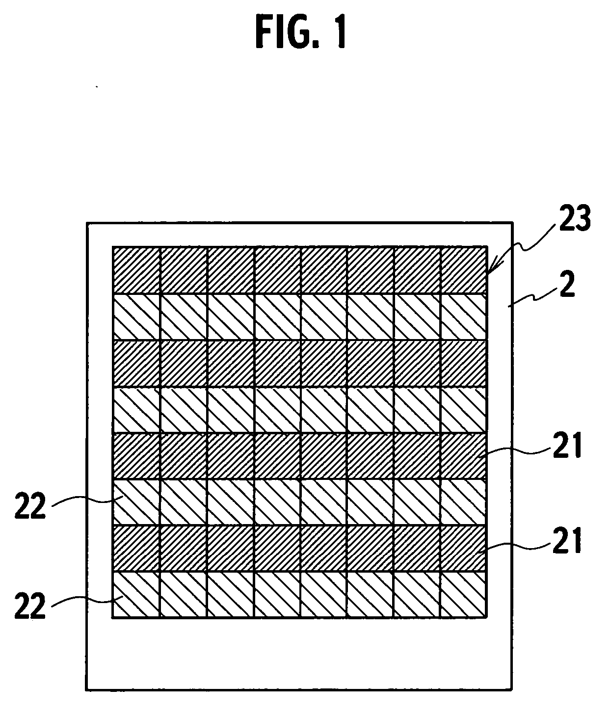
[0031]FIG. 1 is a plan view showing an image capturing function-equipped display device of a first embodiment which is in a state where a plurality of types of light-sensing elements are arranged therein. The display device of this drawing has a picture element region 23 provided with a plurality of picture elements 21 and 22, and light-sensing elements (not shown) provided for the respective picture elements; and has a constitution in which two or more types of light-sensing elements having different optical sensitivities are regularly arranged in the picture element region 23.
[0032] Each light-sensing element is, for example, a gate-controlled diode including a p region, an i region, and an n region. Each low-sensitivity light-sensing element has, for example, a constitution in which p+, p−, n−, and n+ regions are arranged in this order; each high-sensitivity light-sensing element has, for example, a constitution in which p+, p−, and n+ regions are arranged in this order. In this ...
fifth embodiment
[0046] As shown in the plan view of FIG. 9, an image capturing function-equipped display device of a fifth embodiment has a constitution in which a plurality of light-sensing elements having different sensitivities are arranged in the picture element region so as to constitute magic squares. The phrase “to constitute magic squares” herein means repeatedly arranging a certain-number-by-certain-number picture element region in which light-sensing elements having different external appearances (size etc.) or sensitivities are irregularly arranged. This drawing shows, as an example, a state where a three-by-three picture element region in which nine types of light-sensing elements are regularly arranged is repeatedly arranged. Each number in this drawing indicates the sensitivity of the light-sensing element. The value of a photocurrent flowing through the sensor in constant light increases in proportion to the number.
[0047] In the case of the above-described arrangement, signals read b...
seventh embodiment
[0051] In light of this, in an image capturing function-equipped display device of a seventh embodiment, a plurality of light-sensing elements having different sensitivities are arranged such that a magic square is constituted with alternate horizontal lines and with alternate vertical lines. Here, as an example, as shown in the plan view of FIG. 12, nine types of the light-sensing elements are arranged such that each group of the three-by-three picture elements with alternate horizontal lines and with alternate vertical lines constitutes a magic square. In this drawing, diagonal lines indicate positive polarity, and the absence of diagonal lines indicates negative polarity.
[0052] As for the picture element region 41 in this drawing, the picture elements of which numbers are surrounded by circles in the drawing correspond to the three-by-three picture elements with alternate horizontal lines and with alternate vertical lines. The polarities of these picture elements are positive in ...
PUM
 Abstract
Description
Claims
Application Information
 - Generate Ideas
- Intellectual Property
- Life Sciences
- Materials
- Tech Scout
- Unparalleled Data Quality
- Higher Quality Content
- 60% Fewer Hallucinations
Browse by: Latest US Patents, China's latest patents, Technical Efficacy Thesaurus, Application Domain, Technology Topic, Popular Technical Reports.
© 2025 PatSnap. All rights reserved.Legal|Privacy policy|Modern Slavery Act Transparency Statement|Sitemap|About US| Contact US: help@patsnap.com