Capping device for capping a print head

a printing head and capping technology, applied in printing and other directions, can solve the problems of air volume and design disadvantage of drying the nozzle, and achieve the effect of preventing a sudden capping pressur

Inactive Publication Date: 2006-01-12
BENQ CORP
View PDF8 Cites 5 Cited by
  • Summary
  • Abstract
  • Description
  • Claims
  • Application Information

AI Technical Summary

Benefits of technology

[0007] It is therefore a primary objective of the claimed invention to provide a capping device capable of preventing a sudden capping pressure generated during the capping process from destroying the surface tension of ink for solving the above-mentioned problem.

Problems solved by technology

This results in air volume compression so as to generate a sudden increase in pressure.
Unfortunately, the design mentioned above has a disadvantage of drying the nozzle.

Method used


Image

  • Capping device for capping a print head
  • Capping device for capping a print head
  • Capping device for capping a print head

Examples


Embodiment Construction

[0018] Please refer to FIG. 3. FIG. 3 is a perspective drawing of a printer 20 of the present invention. The printer 20 includes an ink cartridge 22 installed on a carrier 24. The ink cartridge 22 contains ink for printing. The carrier 24 can carry the ink cartridge 22 to move on a print track 26, and a print head (not shown in FIG. 3) on the bottom of the ink cartridge 22 can print images on a print medium (not shown in FIG. 3). The print head includes at least one nozzle (not shown in FIG. 3) to jet out ink onto the print medium. The printer 20 further includes a capping device 28 installed on one side of the print track 26. When the ink cartridge 22 finishes printing, the carrier 24 can drive the ink cartridge 22 to the capping device 28 for capping the print head.

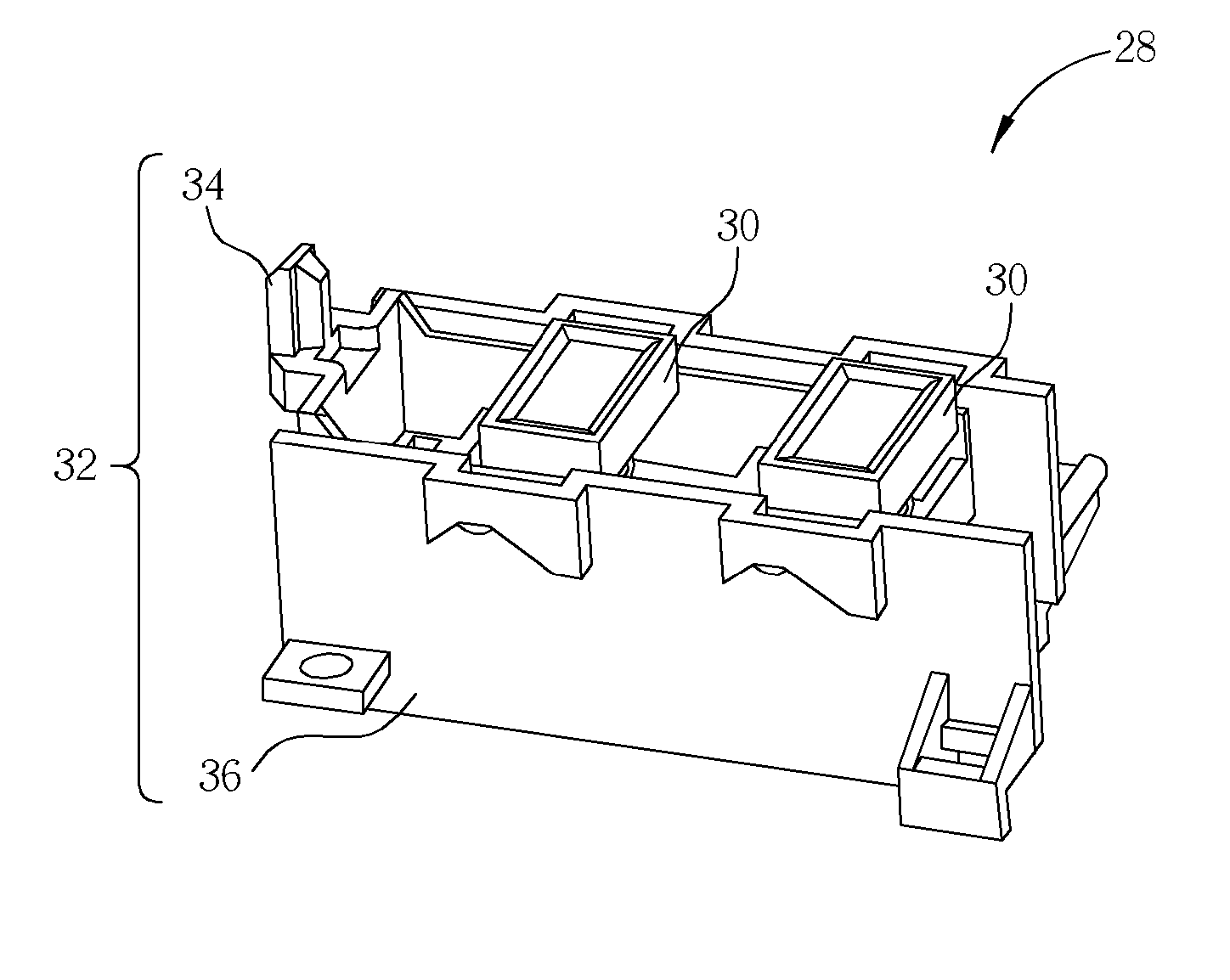
[0019] Please refer to FIG. 4. FIG. 4 is a schematic drawing of the capping device 28 of the present invention. The capping device 28 includes two caps 30, and a supporting structure 32. The supporting structure 32 inc...


PUM


Abstract

A capping device for capping a print head of a printer includes a cap for capping the print head, a supporting structure for mechanically engaging and disengaging the cap with the print head, and an elastic structure installed inside the cap. The top of the cap is lower than the top of the elastic structure. Before the supporting structure engages the cap with the print head, the top of the elastic structure bends outward and contacts the print head in an incomplete sealed manner.

Description

BACKGROUND OF INVENTION [0001] 1. Field of the Invention [0002] The present invention relates to a capping device and more particularly, to a capping device capable of preventing a sudden capping pressure generated during the capping process from destroying the surface tension of ink. [0003] 2. Description of the Prior Art [0004] Ink jet print systems are used for fax machines, printers, photocopiers, or other office appliances. The ink jet print system includes a capping device for capping a print head so as to ensure normal operation of the print head. When the inkjet print system is not used, the capping device is capable of capping the print head to prevent the ink in the nozzles from drying so as to jam the print head. [0005] Please refer to FIG. 1 and FIG. 2. FIG. 1 is a schematic drawing of a conventional capping device 10, and FIG. 2 is a schematic drawing of a cap 12 of the capping device 10. The capping device 10 includes the cap 12, a cap sled 14, and a cap housing 16. Th...

Claims


Application Information

Patent Timeline
Patent Type & Authority Applications(United States)
IPC IPC(8): B41J2/165
CPCB41J2/16508
Inventor HUANG, SHR-HOW
Owner BENQ CORP
Why Eureka
Try Eureka