Exposure system and device production process

a technology of exposure system and production process, applied in the field of exposure system, can solve the problems of deformation in stages and surrounding components, the risk of aforementioned baseline amount shifting during exposure, and the prior art exposure system and device production process still had the problems described below, so as to achieve superior overlay accuracy and inhibit baseline shift

Inactive Publication Date: 2006-01-12
NIKON CORP
View PDF0 Cites 27 Cited by
  • Summary
  • Abstract
  • Description
  • Claims
  • Application Information

AI Technical Summary

Benefits of technology

[0013] In consideration of the aforementioned problems, the object of the present invention is to provide an exposure system and device production process that enables the required temperature control for each component while also being able to control baseline shift.
[0016] Thus, in the exposure system of the present invention, the temperature of the projection optics and substrate stage can be separately and independently controlled in, for example, 1 / 100° C. units by circulating the first liquid in the first control system, while the temperature of the reticle stage can be separately and independently controlled in, for example, 1 / 10° C. units by circulating the second liquid in the second control system. Namely, since the first and second control systems are individually set corresponding to the temperature range required by the projection optics and reticle stage, temperature can be controlled at the level of accuracy required by each component, thereby making it possible to inhibit baseline shift caused by temperature fluctuations.
[0018] Thus, in the exposure system of the present invention, the temperature of the projection optics and substrate stage can be respectively and independently controlled in, for example, 1 / 100° C. units in the first control system by circulating the first liquid under the first circulation conditions, and the temperature of the reticle stage can be respectively and independently controlled in, for example, 1 / 10° C. units in the second control system by circulating the second liquid under the second circulation conditions. Namely, since the first and second control systems are individually set corresponding to the temperature range required by the projection optics and reticle stage, temperature can be controlled at the level of accuracy required by each component, thereby making it possible to inhibit baseline shift caused by temperature fluctuations. At this time, since the first and second circulation conditions are set based on the temperatures of the first and second liquids that are detected before and after circulating through each component, temperature can be controlled with high precision based on temperature changes of the first and second liquids that occur as a result of circulating through each component.
[0020] Thus, in the exposure system of the present invention, temperature can be respectively and independently controlled with the first control system by making the drive sources of the substrate stage and projection optics having a low amount of heat generation or temperature change first control targets, and temperature can be respectively and independently controlled with the second control system by making the drive sources of the reticle stage having a comparatively large amount of heat generation or temperature change second control targets. Namely, since the projection optics and stage drive sources are made to be control targets corresponding to the amount of heat generated or temperature change, temperature can be controlled at the level of accuracy required by each component, thereby making it possible to inhibit baseline shift caused by temperature fluctuations.
[0022] Thus, in the device production process of the present invention, a pattern can be transferred to a substrate in a state in which the required temperature control has been carried out, thereby making it possible to obtain a device having superior overlay accuracy by inhibiting baseline shift caused by temperature fluctuations.

Problems solved by technology

However, there is the risk of the aforementioned baseline amount shifting during exposure (baseline shift) due to the occurrence of thermal expansion and thermal deformation in the alignment system and so forth caused by heat generated accompanying each type of processing.
However, the aforementioned exposure systems and device production processes of the prior art still had the problems described below.
Since scan types scan both the wafer and reticle during exposure (during pattern transfer), both the wafer stage and reticle stage become susceptible to retaining heat due to the effects of the motors and so forth, gradually causing deformation in the stages and surrounding components.
Although stage position is measured using an interference system, if the distance between a moving mirror and reticle change due to deformation of the stage, the baseline ends up shifting resulting in poor overlay accuracy.
In addition, since the temperature of the atmosphere surrounding the stage ends up rising due to the heat generated by the stage, there is also the problem of deterioration of stage positioning accuracy due to the effects of deviations in the interferometer light path.
However, in the case of cooling the wafer stage and reticle stage, which generate considerable heat in 1 / 10° C. units, and the projection optics and alignment system, for which the temperature must be controlled in 1 / 100° C. units, using a single temperature controller, cooling capacity becomes inadequate for the wafer stage and reticle stage that demonstrate large temperature changes if the coolant temperature is controlled based on the temperature of the projection optics.
Conversely, if the coolant temperature is controlled based on the temperature of the wafer stage and reticle stage, it is no longer possible to control the temperature of the projection optics and alignment system with the required level of precision (fineness).
In particular, since the reticle stage moves over a distance and at a speed corresponding to the projection factor with respect to the wafer stage, the amount of heat generated is extremely large, thus making it difficult to manage the temperature of the projection optics and alignment system with the same control system.
In this manner, unless temperature management is adequate, problems occur in which the baseline shift increases and overlay accuracy worsens.

Method used


Image

  • Exposure system and device production process
  • Exposure system and device production process
  • Exposure system and device production process

Examples


first embodiment

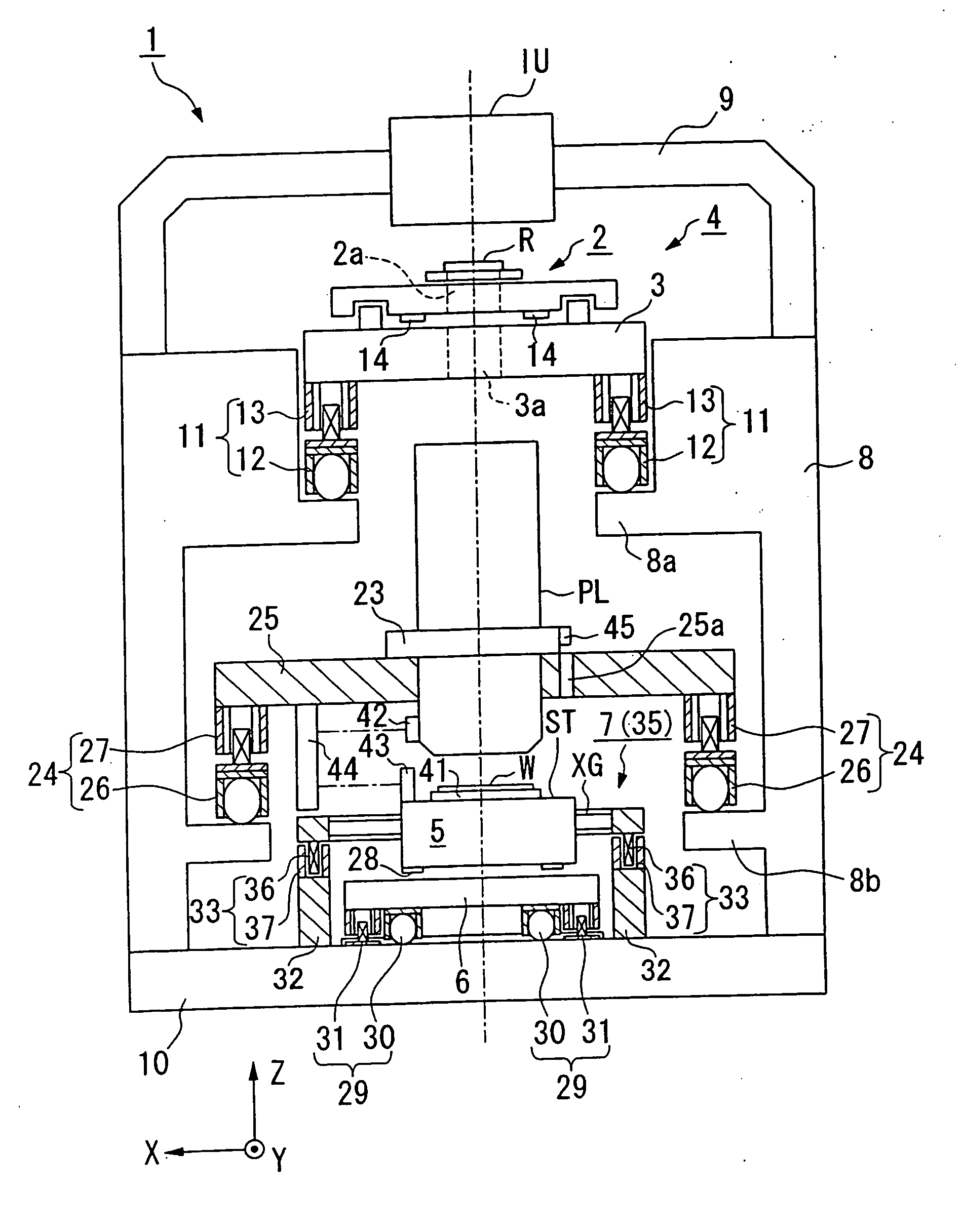
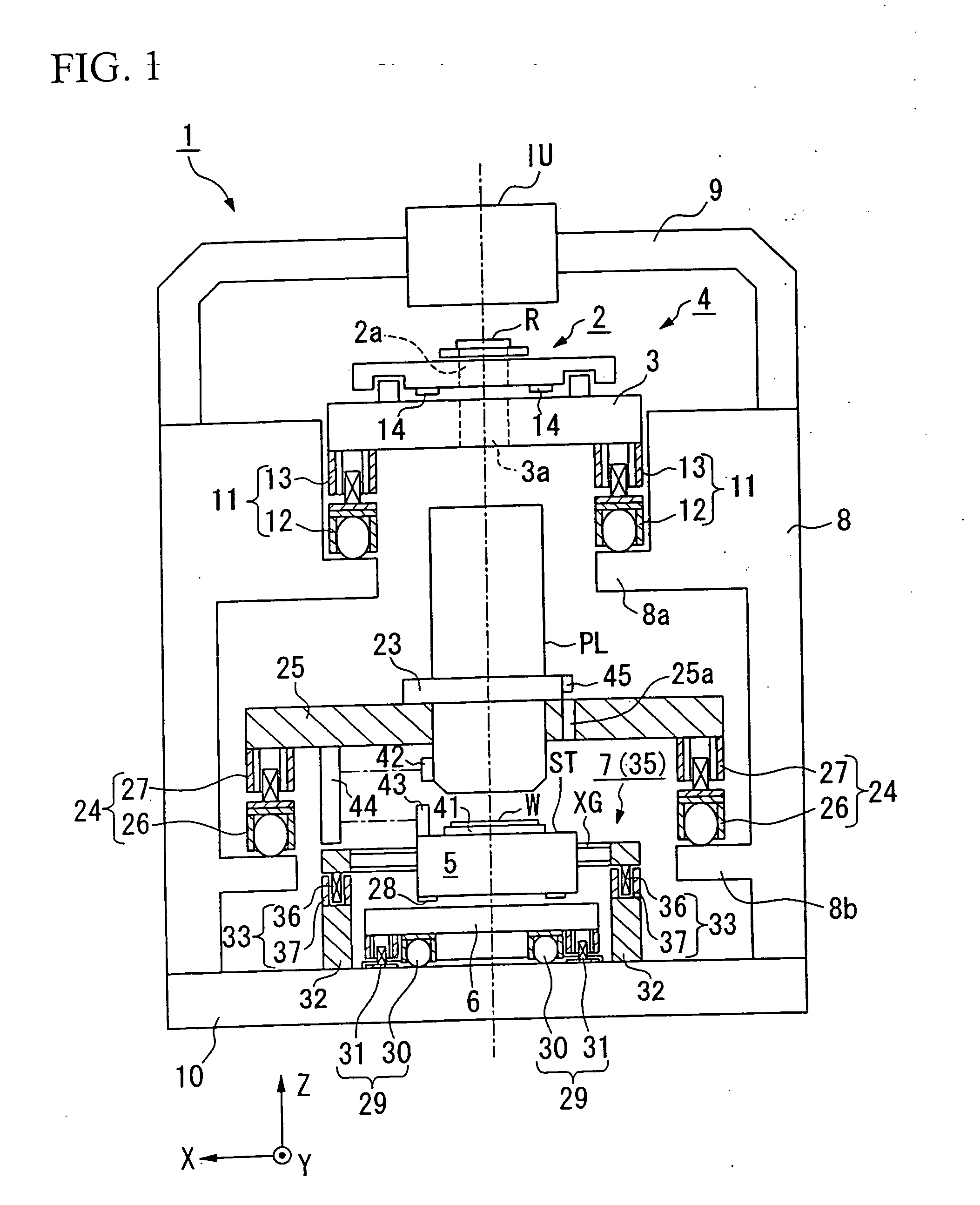
[0034] The following provides an explanation of an exposure system and device production process of the present invention with reference to FIGS. 1 through 7. Here, an explanation is provided using the example of the case of using a scanning stepper for the exposure system that transfers a circuit pattern of a semiconductor device formed on reticle to a wafer while synchronously rotating the reticle and wafer during exposure (during pattern transfer).

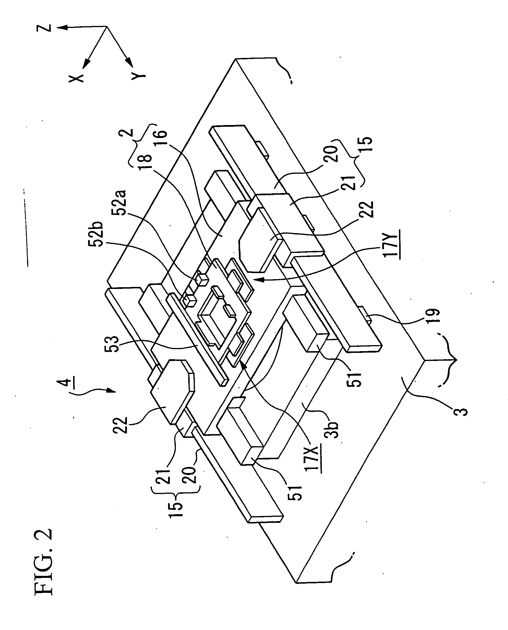
[0035] Exposure system 1 shown in FIG. 1 is roughly composed of illumination optics IU, which illuminates a rectangular (or arc-shaped) illumination region at uniform luminosity on reticle (mask) R with illumination light for exposure from a light source (not shown), a stage system 4, which includes a reticle stage (mask stage) 2 that moves while holding reticle R and a reticle surface plate 3 that supports said reticle stage 2, projection optics PL, which projects illumination light emerging from reticle R onto wafer (substrate) W, a s...

third embodiment

[0098]FIG. 9 shows a projection system as claimed in the present invention.

[0099] In the present embodiment, the projection optics and wafer stage 5 are designated as temperature control targets of first control system 61, while reticle stage 2 is designated as the temperature control target of second control system 62. In first control system 61, the temperatures of circulation system C1, which circulates through projection optics PL and alignment system AL, and circulation system C6, which circulates through wafer stage 5, are controlled by a single temperature regulator 87. This temperature control is carried out sensor 69 detecting the temperature of coolant that circulates through projection optics PL, and controller 67 controlling the driving of temperature regulator 87 based on the detected results. In this case, the temperature of wafer stage 5 is controlled to a range within ±0.01° C. in the same manner as projection optics PL. Furthermore, in second control system 62, reti...

second embodiment

[0100] In the present embodiment as well, the temperature of reticle stage 2, which generates the largest amount of heat, can be controlled independently and separately from projection optics PL and wafer stage 5, which generate comparatively small amounts of heat, and the optimum cooling conditions can be set corresponding to the amount of heat generated by each component. Moreover, in comparison with the second embodiment, since the coolant temperatures of two circulation systems C1 and C6 can be controlled with first control system 61, the system constitution can be simplified.


PUM

PropertyMeasurementUnit
wavelengthaaaaaaaaaa

Abstract

The exposure system of the present invention inhibits baseline shift by carrying out temperature control as required by each composite equipment. This exposure system has a first control system that that sets the temperature of a first liquid, and controls the temperature of an object by circulating the first liquid for which the temperature has been set through at least one object of a projection optics and a substrate stage, and a second control system that sets the temperature of a second liquid independent from the first control system, and controls the temperature of a reticle stage by circulating the second liquid for which the temperature has been set through the reticle stage. The first and second control systems have mutually different setting capacities with respect to the size of the temperature range when setting the temperatures of the liquids.

Description

[0001] This is a Continuation of application Ser. No. 10 / 938,633 filed Sep. 13, 2004, which in turn is a Continuation of International Patent Application No. PCT / JP03 / 03003 filed Mar. 13, 2003. The entire disclosure of the prior applications is hereby incorporated by reference herein in their entireties.TECHNICAL FIELD [0002] The present invention relates to an exposure system that projects and exposes a master pattern onto a wafer or other substrate in a device production process for semiconductor devices, liquid crystal display devices and so forth, and a device production process in which a device pattern is transferred to a substrate. [0003] The present application is based on Japanese Patent Application Nos. 2002-72640 and 2003-2285, the contents of which are incorporated in the present description. BACKGROUND ART [0004] When producing a semiconductor device or liquid crystal display device and so forth in a photolithography process, a projection and exposure system is used tha...

Claims


Application Information

Patent Timeline
Patent Type & Authority Applications(United States)
IPC IPC(8): G03B27/52G03F7/20
CPCG03F7/70716G03F7/70991G03F7/70875
Inventor KOSUGI, JUNICHITANIGUCHI, TETSUOKOBAYASHI, NAOYUKINAGAHASHI, YOSHITOMO
Owner NIKON CORP
Why Eureka
Try Eureka