Heat transfer device, temperature controller, internal combustion engine, exhaust system thereof, and melting furnace

a technology of heat transfer device and temperature controller, which is applied in the direction of generator/motor, machine/engine, mechanical apparatus, etc., can solve the problems of thermionic power generator and uncontrollable temperature of heat sour

Active Publication Date: 2018-04-24
DENSO CORP
View PDF22 Cites 0 Cited by
  • Summary
  • Abstract
  • Description
  • Claims
  • Application Information

AI Technical Summary

Benefits of technology

[0008]When the switching circuit is switched to an OFF state, the heat transfer device of the present disclosure having the above configuration can reduce / restrict the movement of the thermoelectron from the emitter electrode to the collector electrode, and can realize vacuum insulation according to a degree of vacuum of space which separates the emitter electrode and the collector electrode. Thereby, the heat transfer device of the present disclosure can maintain warmth of a heat source from which the heat transfer device transfers heat.
[0009]On the other hand, the heat transfer device of the present disclosure can move the thermoelectron from the emitter electrode to the collector electrode by an amount according to resistance or voltage of a load circuit, when the switching circuit is switched to an ON state. Thereby, the heat transfer device of the present disclosure can control heat transfer, i.e., can emit heat, of the heat source from which the heat transfer device transfers heat.
[0010]Thus, when the switching circuit switches to the ON state or to the OFF state, the heat transfer device of the present disclosure can regulate heat transfer of the heat source, and enables a temperature control of the heat source.

Problems solved by technology

However, since the amount of the thermoelectron emitted from an emitter electrode is dependent on the temperature of the heat source which touches an emitter electrode, the temperature of this heat source is uncontrollable by a thermionic power generator given in the above-mentioned patent document 1.

Method used


Image

  • Heat transfer device, temperature controller, internal combustion engine, exhaust system thereof, and melting furnace
  • Heat transfer device, temperature controller, internal combustion engine, exhaust system thereof, and melting furnace
  • Heat transfer device, temperature controller, internal combustion engine, exhaust system thereof, and melting furnace

Examples


first embodiment

[0018](First Embodiment)

[0019]The first embodiment of the present disclosure is described with reference to the drawings in the following.

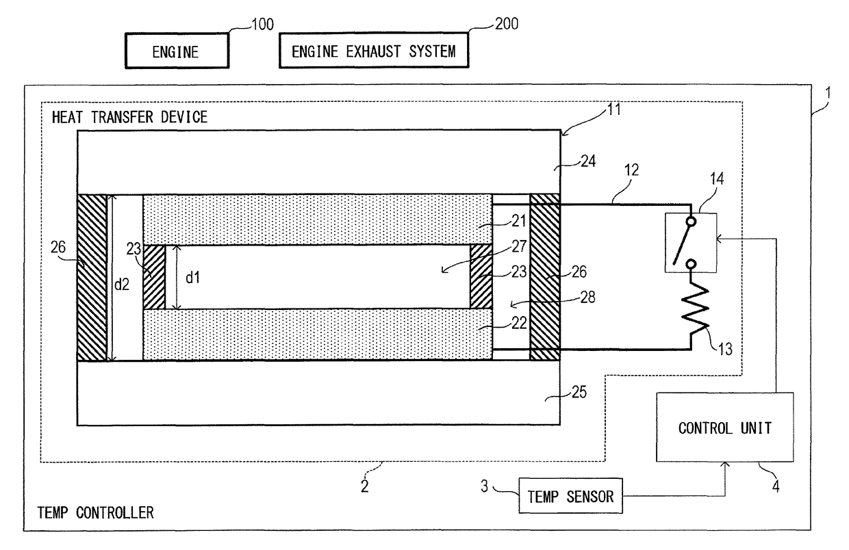
[0020]As shown in FIG. 1, a temperature controller 1 of the present embodiment is installed in an engine exhaust system 200 which discharges the exhaust gas from an internal combustion engine 100 carried in a vehicle to the outside of the vehicle, and is provided with a heat transfer device 2, a temperature sensor 3, and a control unit 4.

[0021]The engine exhaust system 200 is provided with an exhaust pipe (not illustrated) which constitutes a passage of the exhaust gas discharged from the internal combustion engine 100, and a purifier (not illustrated) which purifies the exhaust gas passing through the exhaust pipe by using a catalyst.

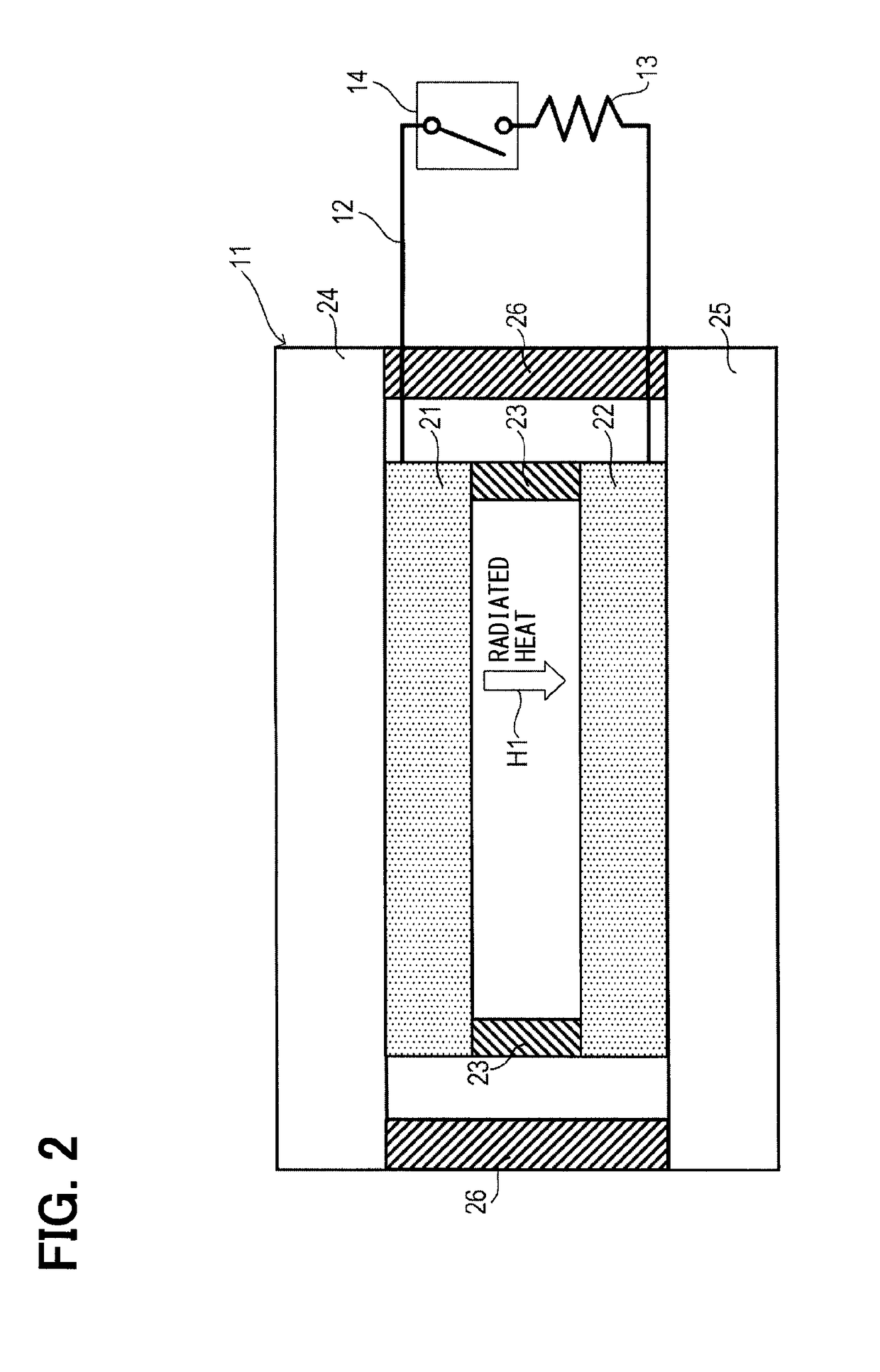
[0022]The heat transfer device 2 is provided with a thermionic power generator 11, also known as a “thermoelectric power generation element,” a wiring 12, a load resistor 13, and a switch 14.

[0023]The thermionic powe...

second embodiment

[0052](Second Embodiment)

[0053]The second embodiment of the present disclosure is described with reference to the drawings in the following. In the second embodiment, description focuses on a difference from the first embodiment.

[0054]As shown in FIG. 4, the temperature controller 1 of the present embodiment is installed in the internal combustion engine 100 carried in a vehicle, and is provided with the heat transfer device 2, the temperature sensor 3, and the control unit 4. The heat transfer device 2 is provided with the thermionic power generator 11, the wiring 12, the load resistor 13, the switch 14, an outer wiring 15, a power supply 16, and an outer switch 17.

[0055]The emitter holder 24 of the thermionic power generator 11 is attached to an outer wall of the combustion chamber of the engine in the vehicle.

[0056]The outer wiring 15 electrically connects the emitter electrode 21 and the collector electrode 22.

[0057]The power supply 16 is arranged on the electric current path be...

third embodiment

[0076](Third Embodiment)

[0077]The third embodiment of the present disclosure is described with the drawings in the following. In the third embodiment, description focuses on a difference from the second embodiment.

[0078]As shown in FIG. 6, the temperature controller 1 of the present embodiment is installed in a melting furnace 300 (e.g., a metal melting furnace or a glass melting furnace), and is provided with the heat transfer device 2, the temperature sensor 3, and the control unit 4.

[0079]The heat transfer device 2 is provided with the thermionic power generator 11, the wiring 12, the load resistor 13, the switch 14, the outer wiring 15, the power supply 16, and the outer switch 17.

[0080]The emitter holder 24 of the thermionic power generator 11 is attached to the outer wall of the melting furnace 300.

[0081]The temperature sensor 3 is attached to the outer wall of the melting furnace 300, and detects the temperature of the melting furnace 300.

[0082]The control unit 4 determines w...


PUM


Abstract

A heat transfer device that includes a thermionic power generator, a wiring, a load circuit, and a switch circuit. The thermionic power generator includes an emitter electrode and a collector electrode facing each other with an inter-electrode gap distance, and converts heat energy into electric energy by capturing, with the collector electrode, a thermoelectron that is emitted from the emitter electrode. The wiring electrically connects the emitter electrode and the collector electrode. The load circuit is connected to an electric current path of by wiring between the emitter electrode and the collector electrode. The switch circuit switches between an ON state and an OFF state.

Description

CROSS REFERENCE TO RELATED APPLICATION[0001]The present application is based on and claims the benefit of priority of Japanese Patent Application No. 2014-148157, filed on Jul. 18, 2014, the disclosure of which is incorporated herein by reference.TECHNICAL FIELD[0002]The present disclosure generally relates to a heat transfer device having a thermionic power generator, as well as a temperature controller, an internal combustion engine, an exhaust system thereof, and a heat furnace all having the thermionic power generator.BACKGROUND INFORMATION[0003]The thermionic power generator which transforms thermal energy into the electrical energy is known by capturing the thermoelectron emitted from an emitter electrode by the collector electrode (see the patent document 1 listed below).[0004](Patent document 1) JP 2004-349398 A[0005]However, since the amount of the thermoelectron emitted from an emitter electrode is dependent on the temperature of the heat source which touches an emitter el...

Claims


Application Information

Patent Timeline
Patent Type & Authority Patents(United States)
IPC IPC(8): H02N3/00H01L37/00F01N5/02H01L35/30
CPCF01N5/025H01L35/30H02N3/00H01L37/00F01N13/146H01J45/00F01N2260/08Y02T10/12H10N10/13H10N15/00
Inventor KIMURA, YUJIKATAOKA, MITSUHIROSOBUE, SUSUMU
Owner DENSO CORP
Why Eureka
Try Eureka