Oocyte and embryo handling apparatus

Active Publication Date: 2005-04-05
THE COOPER CO GLOBAL HLDG LP
View PDF13 Cites 9 Cited by
  • Summary
  • Abstract
  • Description
  • Claims
  • Application Information

AI Technical Summary

Benefits of technology

According to a third aspect of the present invention there is provided a method of oocyte recovery including the steps of connecting an aspiration tube and a flushing tube to an oocyte recovery needle, maintaining the warmth of the tubes along

Problems solved by technology

One problem with the apparatus used in this technique is that the temperature of the liquid used to help flush out the oocytes from the patient can fall below the ideal level, especially if the procedure is delayed.
Similar problems exist when handling embryos.

Method used


Image

  • Oocyte and embryo handling apparatus
  • Oocyte and embryo handling apparatus
  • Oocyte and embryo handling apparatus

Examples


Embodiment Construction

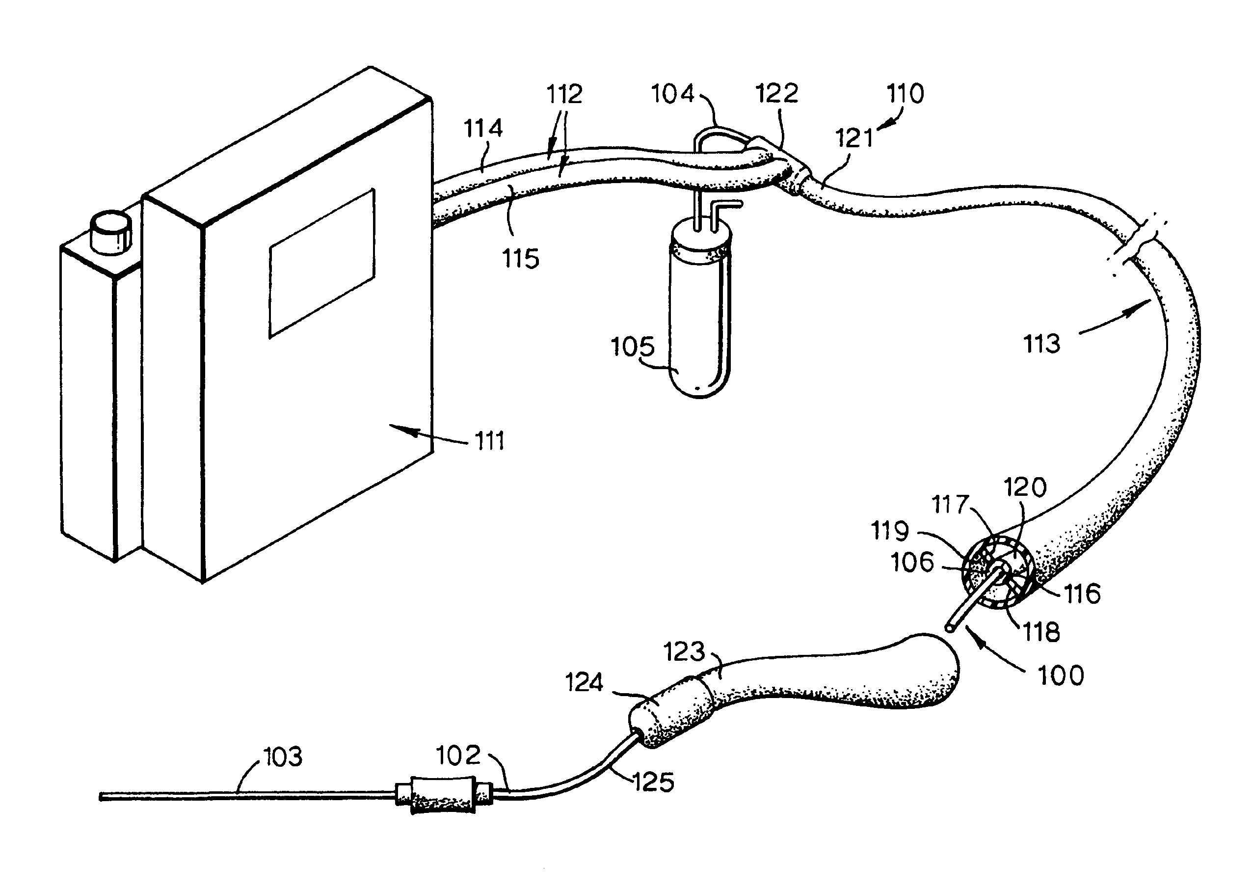
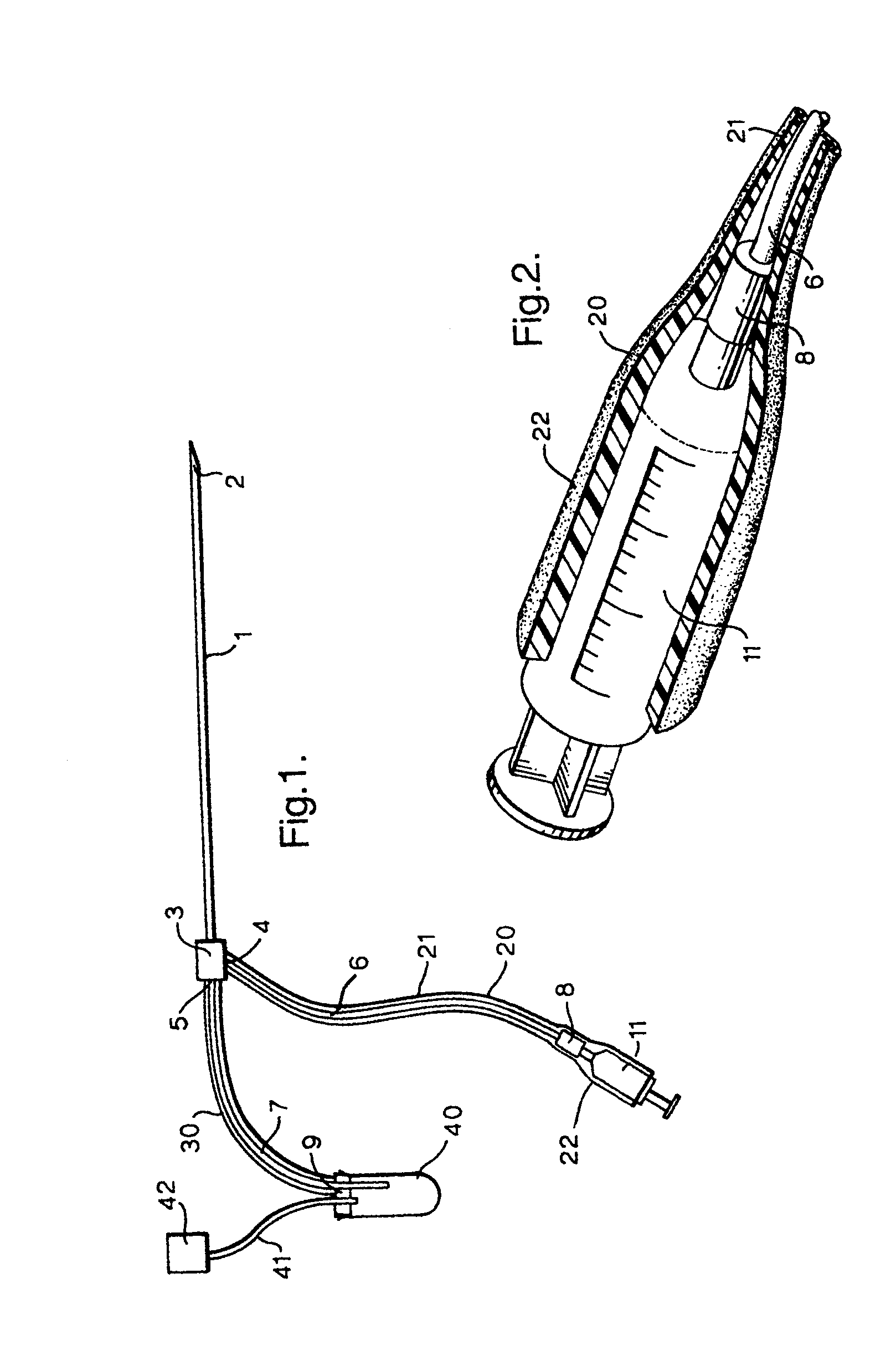
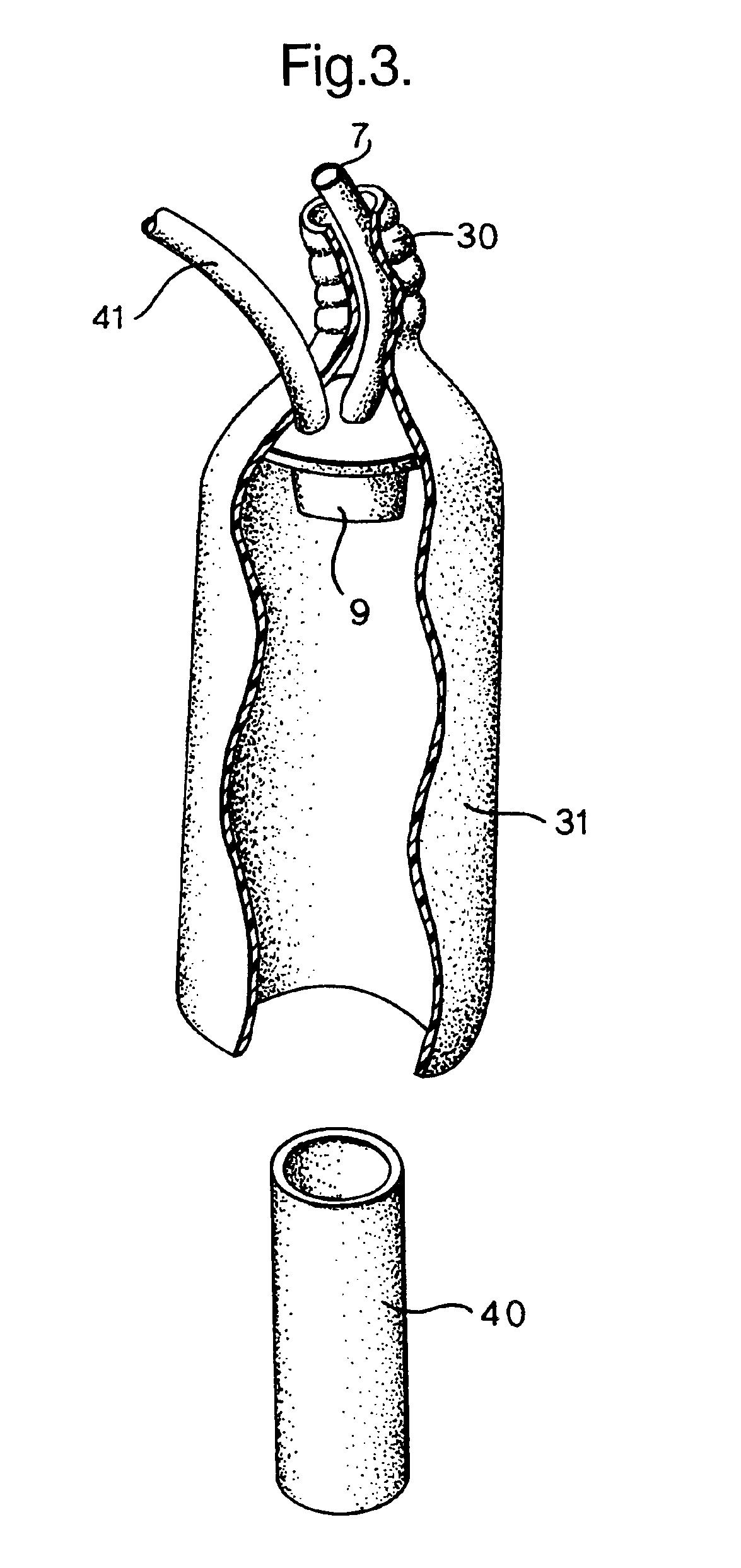
With reference first to FIG. 1 the apparatus includes a conventional dual-lumen oocyte recovery needle 1 having a forward, patient end tip 2 and a rear end hub 3. The two lumens within the needle are respectively for supplying flushing liquid and for passage in the opposite direction of aspirated materials including oocytes and follicle fluid. The flushing and aspiration lumens in the needle connect with respective ports 4 and 5 on the hub 3. Attached with the flush and suction ports 4 and 5 are respective tubes 6 and 7. The flushing tube 6 is terminated by a connector 8. The aspiration tube 7 extends through a bung 9 fitted into the neck of a test tube 40. A second tube 41 extends through the bung 9 into the test tube 40 at one end and is connected at its other end with a vacuum pump 42.

The apparatus further includes a syringe 11 connected to the flushing tube 6 and containing a suitable flushing fluid warmed to body temperature of about 37° C.

The apparatus is completed by two ther...


PUM


Abstract

Oocyte extraction apparatus or embryo replacement apparatus has a flexible tube along which the oocyte or embryo passes. The tube extends along an outer jacket which maintains the temperature within the tube. The jacket may be thermally insulating or it may be heated such as with warmed liquid.

Description

BACKGROUND OF THE INVENTIONThis invention relates to oocyte and embryo handling apparatus.Conventionally, an oocyte is extracted from a follicle using a needle to which suction is applied so that the oocyte is aspirated into a test tube or other receptacle. Often a flushing liquid is supplied along a secondary lumen of the needle to assist removal. Once the oocyte has been extracted, it is transferred to a suitable receptacle.One problem with the apparatus used in this technique is that the temperature of the liquid used to help flush out the oocytes from the patient can fall below the ideal level, especially if the procedure is delayed. Also, the temperature of the oocyte can fall appreciably during its passage along the needle, its associated tubing and into the test tube. Similar problems exist when handling embryos.BRIEF SUMMARY OF THE INVENTIONIt is an object of the present invention to provide alternative apparatus for use in handling an oocyte or embryo.According to one aspec...

Claims


Application Information

Patent Timeline
IPC IPC(8): A61B17/42A61B17/435C12M1/38A61B18/00
CPCA61B17/435A61B2018/00101A61B2018/00041
Inventor BATEMAN, TIMOTHYNASH, JOHN EDWARD
Owner THE COOPER CO GLOBAL HLDG LP
Why Eureka
Try Eureka