Methods and systems for condensation control

a technology of condensation control and methods, applied in vehicle heating/cooling devices, vehicle cleaning, vehicle components, etc., can solve the problems of reducing the efficiency of condensation control, so as to achieve more effective and faster defrosting and increase the capacity to absorb water

Active Publication Date: 2017-06-20
FORD GLOBAL TECH LLC
View PDF44 Cites 5 Cited by
  • Summary
  • Abstract
  • Description
  • Claims
  • Application Information

AI Technical Summary

Benefits of technology

[0002]Vehicles may be configured with defrosting systems to clear condensation and / or thaw frost from the windshield, back window, and / or side windows of the vehicle. Defrosting systems may include components, such as blowers and fans that are shared with a vehicle heating ventilation and air conditioning (HVAC) system and an engine cooling circuit. For primary defrosting, heat is provided by the vehicle's engine coolant via the heater core. Specifically, fresh air is blown through the heater core and then ducted to and distributed over the interior surface of the windshield by a blower. In addition to fans and blowers of the HVAC system, an air conditioner may also be operated during defrosting to dehumidify the air blown by the fans and blowers. The dehumidification makes the defrosting more effective and faster since dried air has a greater capacity to absorb water from the glass at which it is directed. Secondary defrosting, often used on the back and / or side mirrors, typically consists of multiple resistive conductors embedded in or on the glass. When power is applied, these conductors heat up, thawing ice and evaporating condensation from the glass.
[0004]The inventors herein have recognized that the heat generated at the HVAC system during a defrosting mode can be advantageously used during an engine cold-start to expedite warming of the charge air cooler and the engine. In one example, this may be achieved by a method for an engine comprising: responsive to a vehicle defrost condition, operating an air conditioner, and rejecting heat from a first cooling circuit to engine intake air, the first cooling circuit coupled to the air conditioner, a charge air cooler, and a radiator, the first cooling circuit not coupled to the engine. In this way, while the air conditioner is engaged to dehumidify the cabin during defrosting, the heat rejected by the air conditioner is advantageously used to expedite warming of the engine and the charge air cooler.
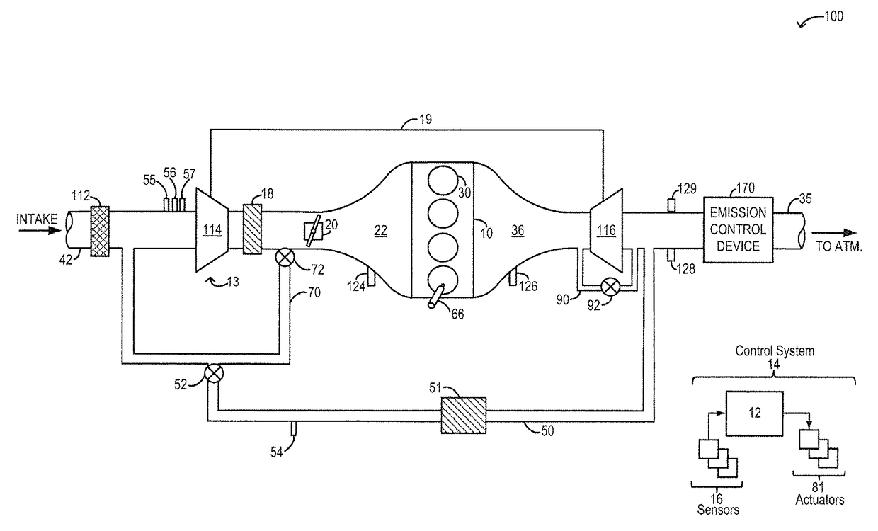
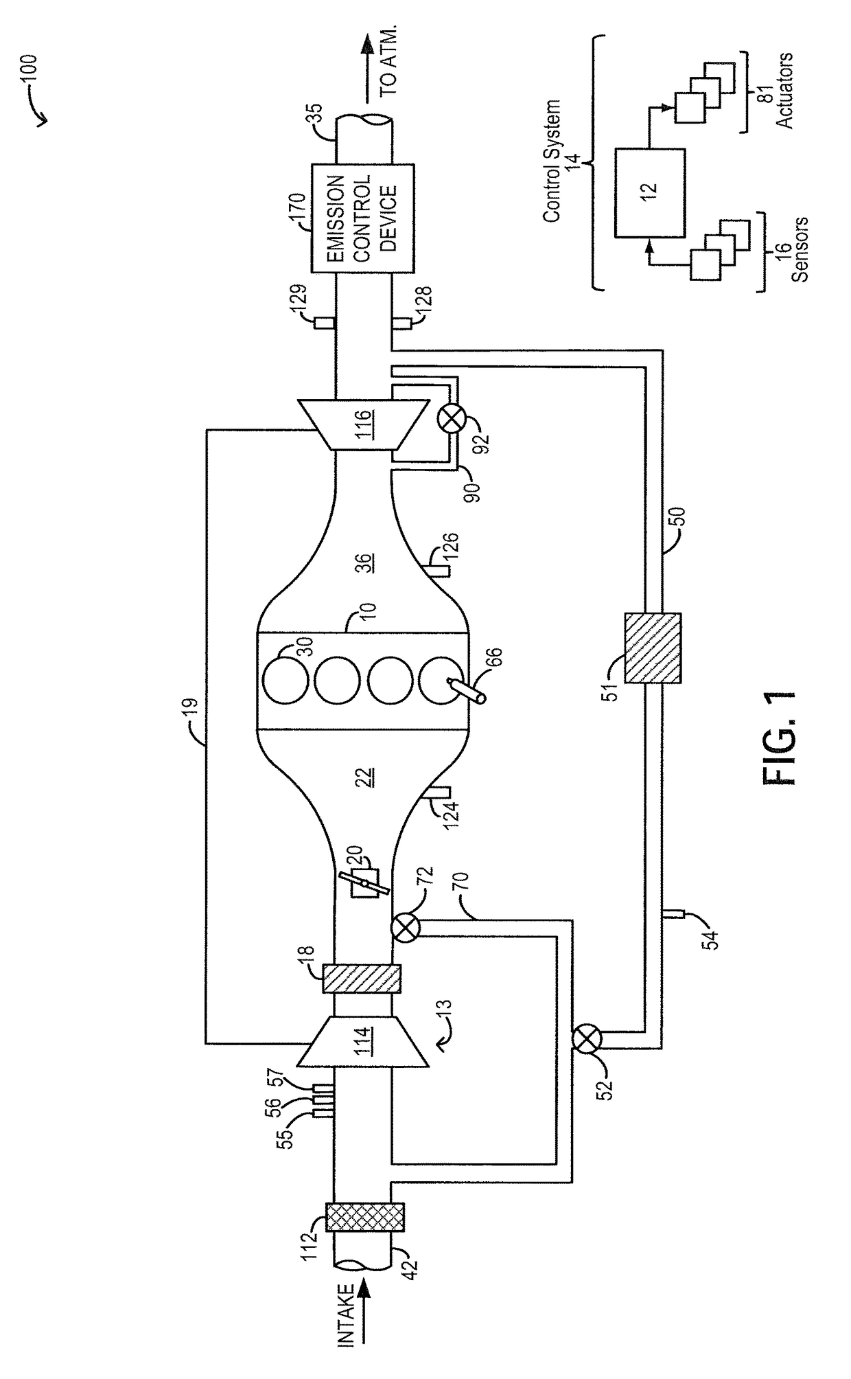
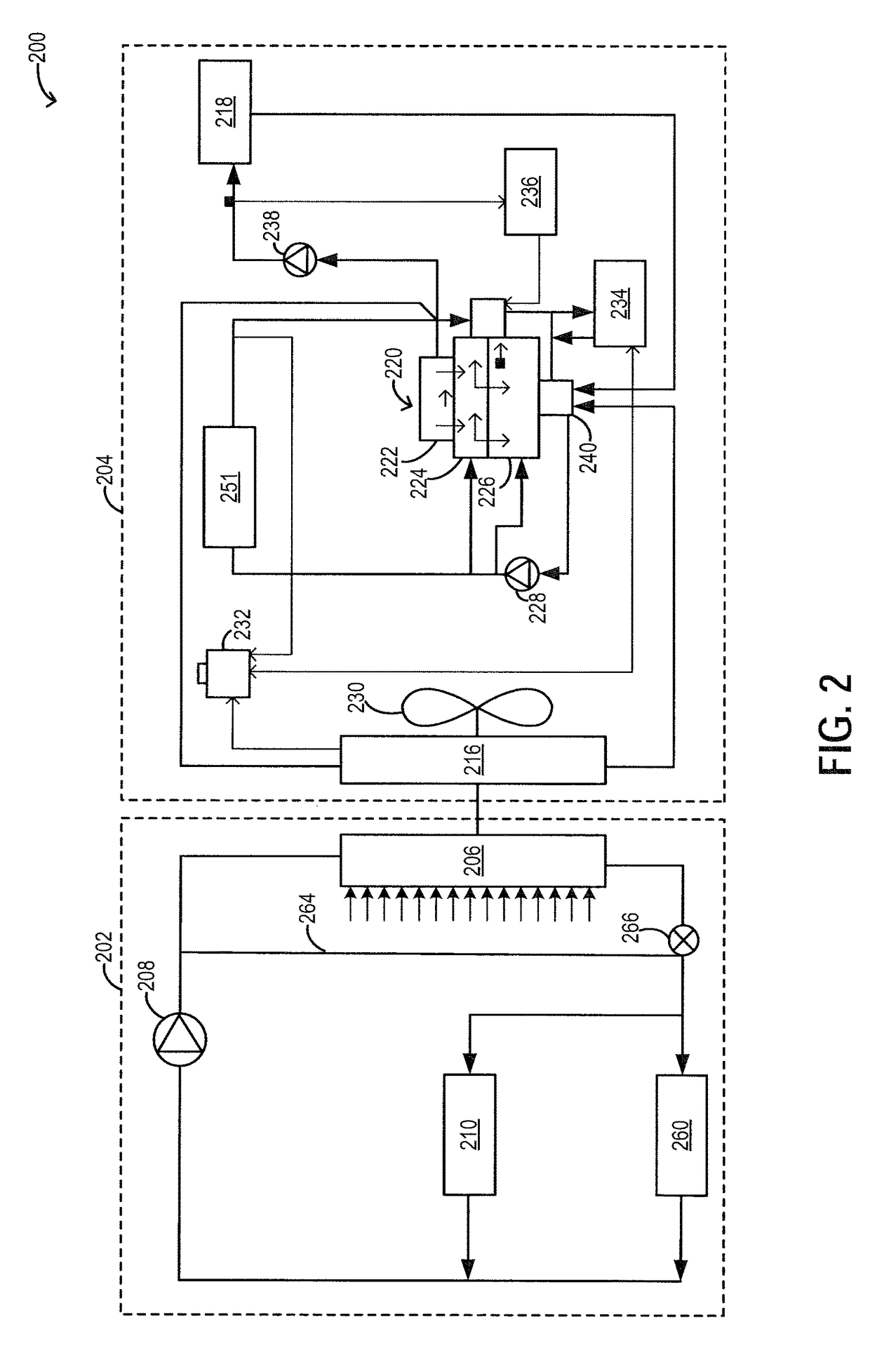
[0005]For example, an engine system may include a first cooling circuit coupled to an air conditioner (or HVAC system), a charge air cooler, a first coolant pump, and a radiator. The radiator may be coupled to the remaining components of the first cooling circuit via a thermostat valve such that when temperature of coolant flowing through the first cooling circuit is lower than a threshold, the thermostat valve remains closed and coolant flows through the circuit while bypassing the radiator. Then, when coolant temperature is above the threshold, the thermostat valve opens to allow coolant to flow through the radiator. As such, the first cooling circuit may constitute a low temperature loop. A second, different cooling circuit may include the engine and a fan, the second circuit constituting a high temperature loop. During vehicle defrosting conditions, the air conditioner (AC) may be operated to dehumidify the cabin air. Heat absorbed from the evaporator from the condensing cabin moisture during dehumidification is rejected to the water cooled AC condenser in the low temperature cooling circuit thereby warming the coolant. The first coolant pump may be operated to flow warmed coolant in the first cooling circuit through the AC (where heat is picked up) and then through a charge air cooler (CAC) while bypassing the radiator. By bypassing the low temperature radiator, no heat is lost to the atmosphere and the warm coolant is able to warm the CAC. The warm CAC in turn warms the aircharge flowing there-through. Once the coolant in the first cooling circuit is sufficiently hot (e.g., above a threshold), the thermostat valve may open and coolant may be pumped around the first cooling circuit through the radiator, allowing heat to be lost to the environment, and enabling temperature control of the first cooling circuit.
[0006]Expedited heating of the CAC provides multiple benefits. First, it expedites engine warm-up by heating the intake aircharge received in the engine, which in turn improves the efficiency of defrosting. Second, by increasing the temperature at the CAC, condensation issues at the CAC are reduced. In addition, low pressure EGR can be introduced earlier without condensation concerns. As such, once EGR is introduced, heat rejected by the EGR cooler into the second cooling circuit further expedites engine warm-up. In this way, defrost heat may be recovered and added to a CAC during cold ambient conditions to expedite warming of the CAC and engine. By operating the engine with warmer air, particulate matter (PM), CO and hydrocarbon (HC) emissions are reduced, and by extending the range of EGR operation, fuel economy benefits are also achieved.

Problems solved by technology

As an example, the engagement of the air conditioner to dehumidify the cabin air results in condenser heat being rejected to the atmosphere during cold ambient conditions.
This heat is lost to the environment without being used.
Cold ambient conditions can also overcool the refrigerant (or coolant) in the cooling circuit and create freezing concerns.
Since the defrosting mode requires hot air that has been heated via the engine cooling circuit, efficient defrosting may be delayed until the engine has sufficiently warmed.
Ironically, since engine heat is sent to the cabin to heat the cool air, engine warm-up during defrosting may be slower than when defrosting is not required.
When condensation accumulates in the intake system the potential for engine misfires and NVH issues increases.

Method used


Image

  • Methods and systems for condensation control
  • Methods and systems for condensation control
  • Methods and systems for condensation control

Examples


Embodiment Construction

[0012]Methods and systems are provided for recovering heat from an air conditioning system coupled to an engine, such as the engine system of FIG. 1, to warm charge flowing through a charge air cooler (CAC). In doing so, intake aircharge and coolant flowing though the charge air cooler's cooling circuit (such as the circuit of FIG. 2), can be warmed. An engine controller may be configured to perform a control routine, such as the routine of FIG. 3, to recover defrost heat by circulating coolant through a CAC bypassing a radiator during cold conditions. EGR delivery may be initiated once the CAC has been sufficiently warmed. An example adjustment is shown with reference to FIG. 4.

[0013]FIG. 1 schematically shows aspects of an example engine system 100 including an engine 10. In the depicted embodiment, engine 10 is a boosted engine coupled to a turbocharger 13 including a compressor 114 driven by a turbine 116. Specifically, fresh air is introduced along intake passage 42 into engine...


PUM


Abstract

Methods and systems are provided for reducing condensate accumulation at a charge air cooler (CAC) during cold ambient conditions. During defrosting conditions, an air conditioner may be operated to dehumidify a cabin space while heat is rejected into a cooling circuit. Warm coolant may be directed to a CAC bypassing a radiator to expedite CAC heating.

Description

FIELD[0001]The present application relates to methods and systems for using heat from an air conditioning system to expedite heating of a charge air cooler.BACKGROUND AND SUMMARY[0002]Vehicles may be configured with defrosting systems to clear condensation and / or thaw frost from the windshield, back window, and / or side windows of the vehicle. Defrosting systems may include components, such as blowers and fans that are shared with a vehicle heating ventilation and air conditioning (HVAC) system and an engine cooling circuit. For primary defrosting, heat is provided by the vehicle's engine coolant via the heater core. Specifically, fresh air is blown through the heater core and then ducted to and distributed over the interior surface of the windshield by a blower. In addition to fans and blowers of the HVAC system, an air conditioner may also be operated during defrosting to dehumidify the air blown by the fans and blowers. The dehumidification makes the defrosting more effective and ...

Claims


Application Information

Patent Timeline
Patent Type & Authority Patents(United States)
IPC IPC(8): B60S1/02B60H1/06B60H1/00
CPCB60S1/023B60H1/00314B60H1/06
Inventor ULREY, JOSEPH NORMANGOPAL, RAVIKATRAGADDA, SUNIL
Owner FORD GLOBAL TECH LLC
Why Eureka
Try Eureka