
Ergonomic hand-mounted illumination device

a technology of illumination device and hand, which is applied in the direction of lighting device details, lighting support devices, lighting and heating apparatus, etc., can solve the problems too large illumination devices, and most subject to potentially damaging forces, etc., and achieve the effect of affecting hand comfor

Inactive Publication Date: 2006-01-12
BLACKBURN PAUL C
View PDF47 Cites 34 Cited by
  • Summary
  • Abstract
  • Description
  • Claims
  • Application Information

AI Technical Summary

Benefits of technology

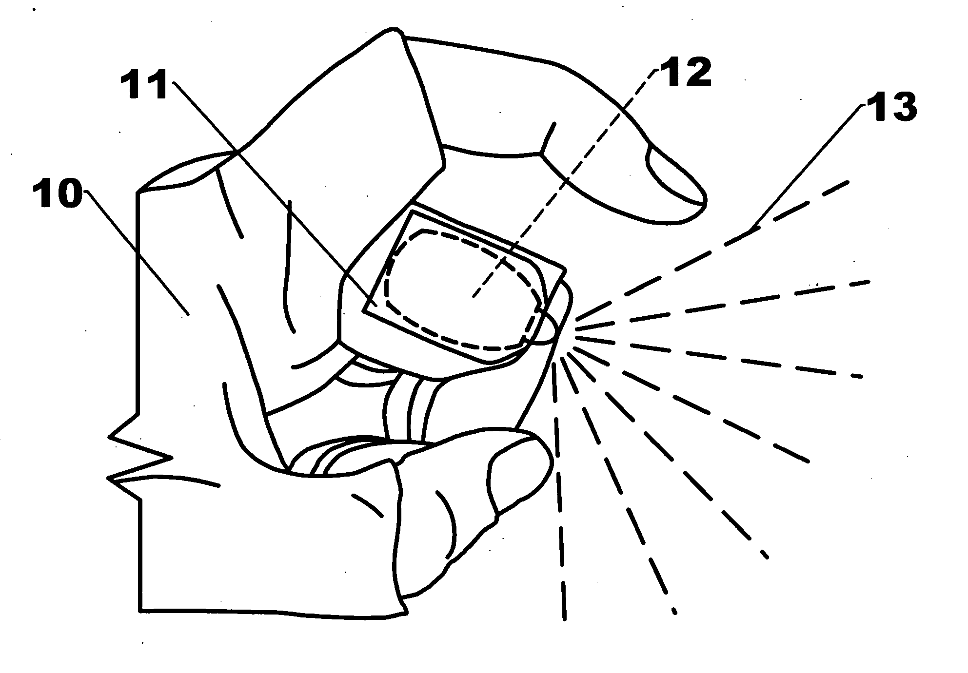
[0016] My hand-mounted illumination device differs fundamentally from all prior art in a simple yet critical way: it places the illumination device's point of light emission between two adjacent fingers such that the point of light emission is in whole or in part between the fingers when the fingers are extended alongside each other. As described below, this placement overcomes the inherent limitations of the prior art without adversely impacting hand comfort. In particular, a between-the-finger location for the point of light emission offers a number of advantages, including but not limited to the following.
[0017] First, the adjacent fingers protect and cover the point of light emission as well as any illumination components located between the fingers, thereby reducing the risk of damage to the illumination device and the risk of personal injury caused by snagging of the device. This shielding action is particularly effective when the hand is made into a fist or when grasping, which are also the circumstances during which hand lights are most subject to potentially damaging forces.

Problems solved by technology

This shielding action is particularly effective when the hand is made into a fist or when grasping, which are also the circumstances during which hand lights are most subject to potentially damaging forces.
In the past, illumination devices were too large to fit comfortably between the fingers and provide useable light.

Method used


Image

  • Ergonomic hand-mounted illumination device
  • Ergonomic hand-mounted illumination device
  • Ergonomic hand-mounted illumination device

Examples


Embodiment Construction

[0067] The present invention overcomes the limitations of the prior art by placing the point of light emission of an illumination device in the area between two adjacent fingers such that the point of light emission is in whole or in part between the fingers when the fingers are extended and positioned alongside each other. A number of embodiments of the present invention can serve to hold the point of light emission between the fingers.

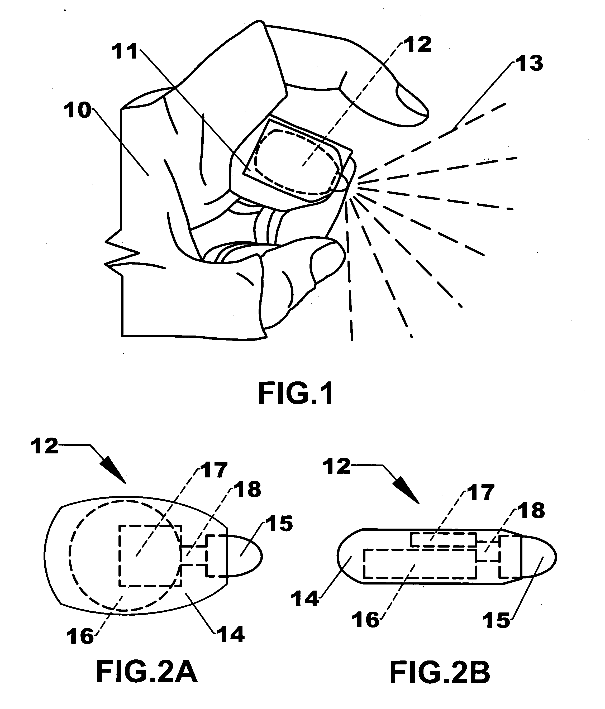
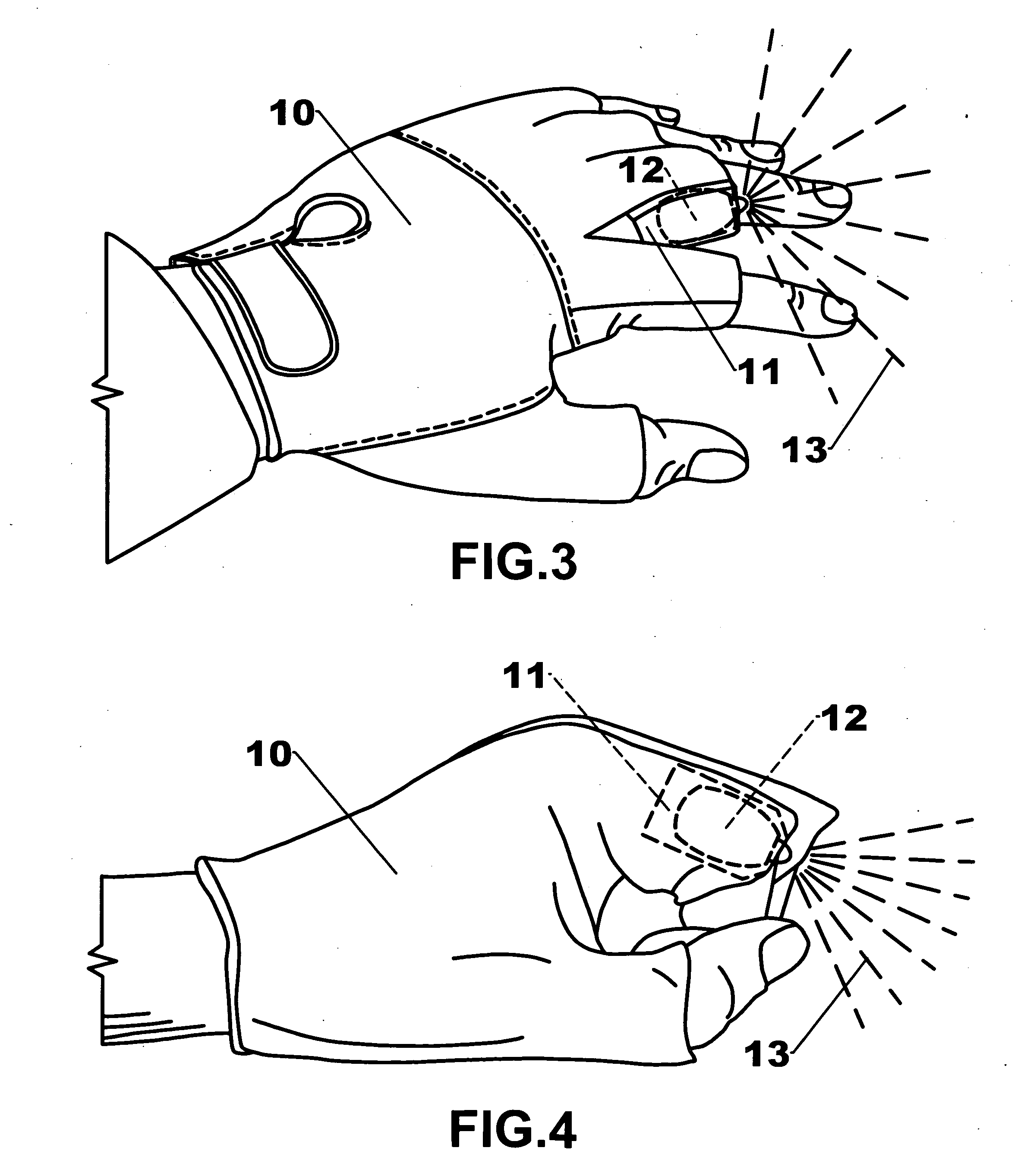
[0068]FIGS. 1, 3, 4, and 5 illustrate a preferred embodiment of the present invention. The hand-mounted illumination device comprises an illumination device 12 and a partial fingered glove 10 with illumination device 12 inserted into a finger pocket 11 located on the side of the second or middle finger of partial fingered glove 10, such that illumination device 12 projects light between the fingers, under the fingers and hand, around the fingertips, and distally of the hand. Partial fingered glove 10 and finger pocket 11 may be fabricated from a var...


PUM


Abstract

A hand-mounted illumination device wherein the point of light emission of an illumination device (12) is disposed between two adjacent fingers, such that the point of light emission is protected by the fingers and illuminates areas between the adjacent fingers, under the fingers and hand, around the fingertips, and distally of the hand. The point of light emission is attached to the side of a finger by means of a partial-fingered glove (10) or a strap (23). Illumination device (12) components, comprising an electrical energy storage device (16), a switch (17), a light-emitting device (15), an electric cable (18), a finger housing (14), a light transmission device (26), and a hand housing (27), may be disposed between the two adjacent fingers, elsewhere on the hand, or in locations not on the hand, provided that the point of light emission of illumination device (12) is disposed between the two adjacent fingers. The illumination device (12) may be operated using the hand to which it is attached.

Description

CROSS REFERENCE TO RELATED APPLICATIONS [0001] Not Applicable. FEDERALLY SPONSORED RESEARCH [0002] Not Applicable. SEQUENCE LISTING OR PROGRAM [0003] Not Applicable. FIELD OF THE INVENTION [0004] The invention relates to hand-mounted illumination devices. BACKGROUND OF THE INVENTION [0005] Hand-mounted illumination devices offer a combination of advantages that overcome limitations inherent in hand-held, head-mounted, and arm-mounted illumination devices, including but not limited to the following. Hand-held illumination devices monopolize the hand that holds them, must be located and retrieved from storage prior to use, and are subject to loss before, during, and after use. Once activated, head-mounted illumination devices free both hands for use but light a much larger area than necessary, add bulk to the head, apply uncomfortable pressure to the head, are difficult to attach securely to the head absent a chin strap, require moving a hand away from the work area for operation, inc...

Claims


Application Information

Patent Timeline
Patent Type & Authority Applications(United States)
IPC IPC(8): F21V21/08
CPCA41D19/0157
Inventor BLACKBURN, PAUL C.
Owner BLACKBURN PAUL C
Learn More