

Directly modulated laser having a variable light reflector
a laser and light reflector technology, applied in the field of light sources, can solve the problems of limiting the upper frequency at which the optical output of a dml can be modulated in this manner, and significant reduction of the operational lifetime of the laser, and achieve the effect of high frequency
- Summary
- Abstract
- Description
- Claims
- Application Information
AI Technical Summary
Benefits of technology
Problems solved by technology
Method used
Image

Examples
Embodiment Construction
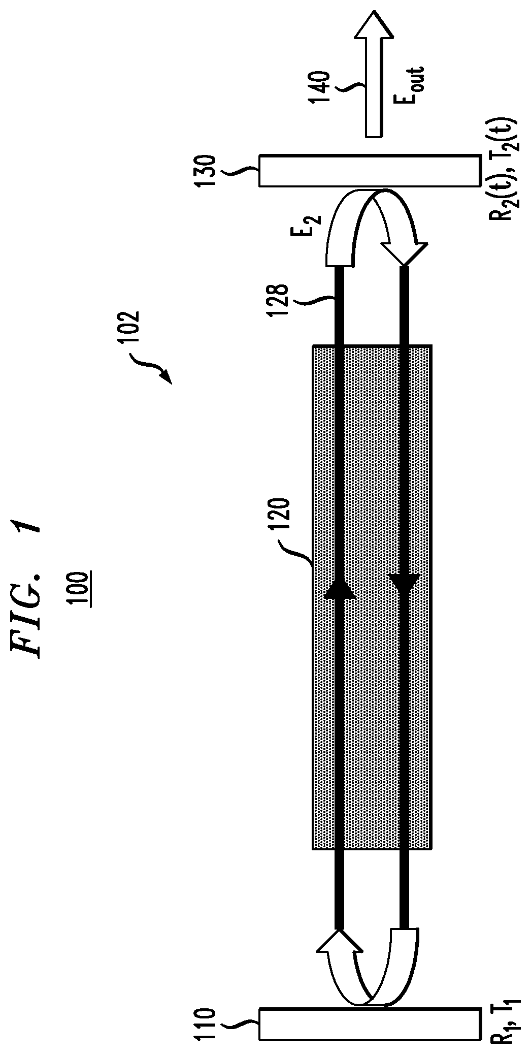
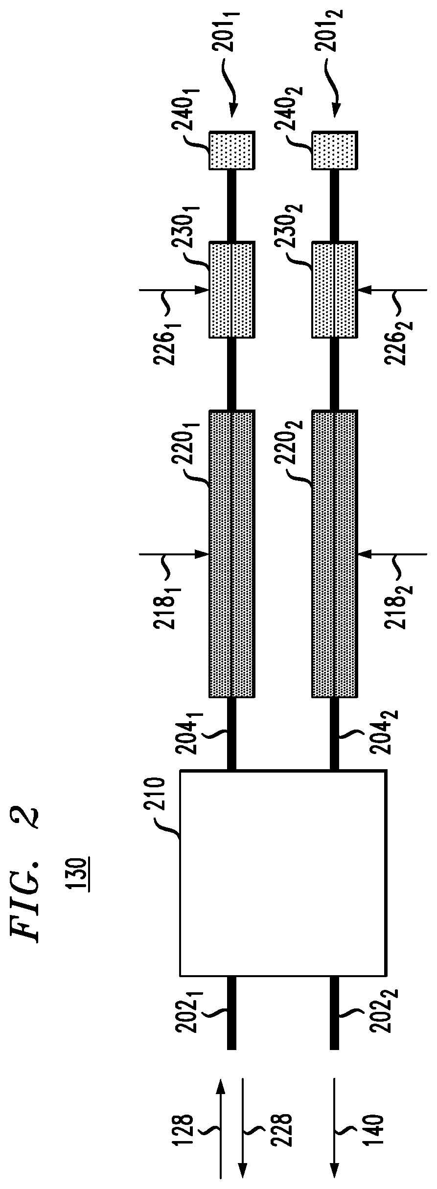
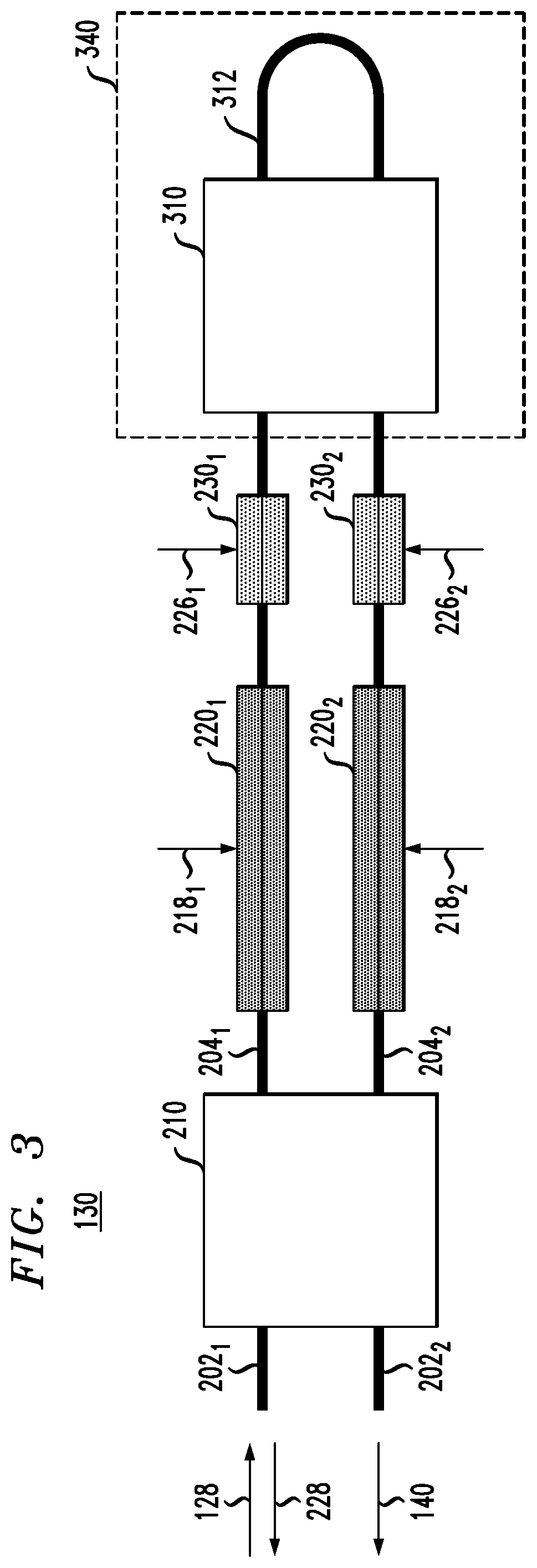
[0004]At least some of the above-indicated problems in the state of the art are addressed by various embodiments of a directly modulated semiconductor laser whose optical output can be modulated by varying the transmittance of an end reflector of the laser cavity. In an example embodiment, the end reflector can be implemented using a lightwave circuit in which optical waveguides are arranged to form an optical interferometer. At least one of the optical waveguides may include a waveguide section configured to modulate the phase of an optical beam passing therethrough in response to an electrical radio-frequency drive signal in a manner that causes the transmittance and reflectance of the end reflector to be modulated accordingly. Advantageously, relatively high (e.g., >10 GHz) phase and / or amplitude modulation speeds of the optical output can be achieved in this manner to circumvent the inherent modulation-speed limitations of the laser's gain medium.
[0005]According to an example em...
PUM
| Property | Measurement | Unit |
|---|---|---|
| frequencies | aaaaa | aaaaa |
| frequencies | aaaaa | aaaaa |
| frequency | aaaaa | aaaaa |
Abstract
Description
Claims
Application Information