Stage lighting methods and apparatus

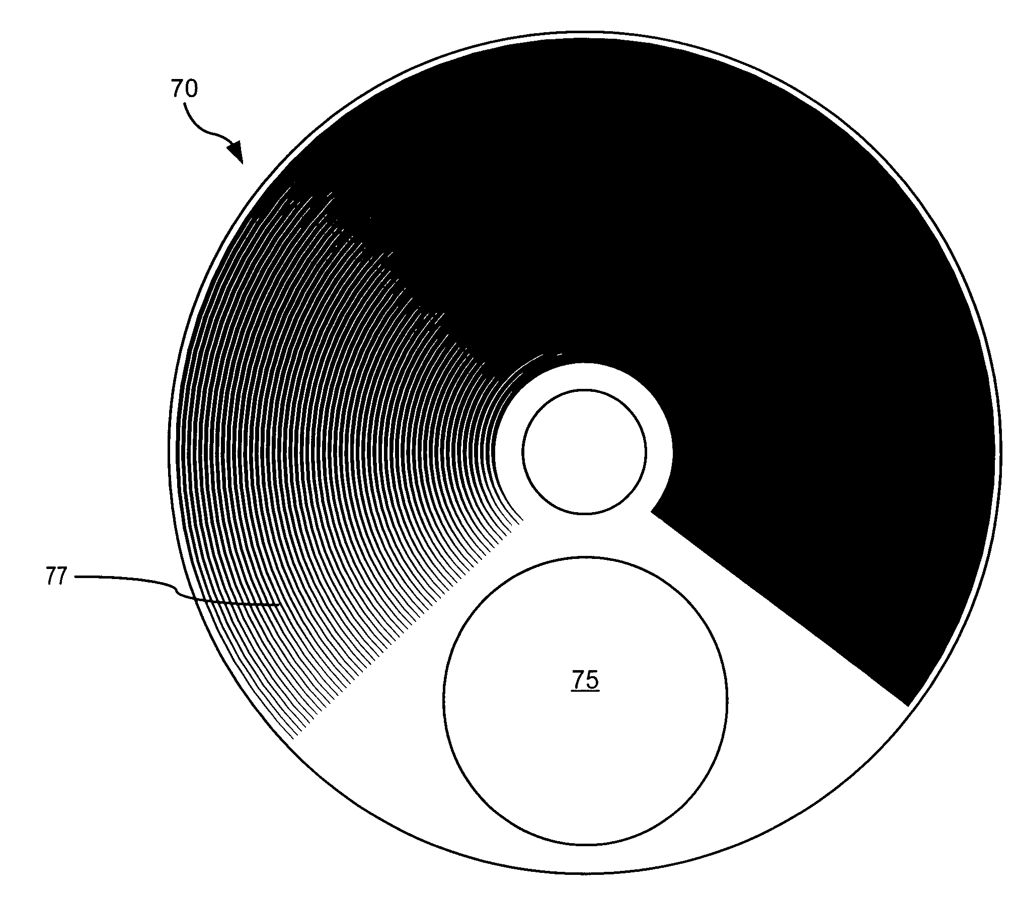
a technology of stage lighting and apparatus, applied in lighting applications, lighting and heating apparatus, spectral modifiers, etc., can solve problems such as loss of energy in the projected beam, inability to achieve the desired goal, and inability to see and image patterns 77/b>

Active Publication Date: 2006-01-12
WHITEROCK DESIGN
View PDF38 Cites 37 Cited by
  • Summary
  • Abstract
  • Description
  • Claims
  • Application Information

AI Technical Summary

Benefits of technology

[0016] According to one implementation a spot luminaire includes a light source for emitting a beam of light and a projection lens configured to project the beam of light towards a distant target. A first field stop, through which the beam of light passes, is positioned between the light source and the projection lens. A filter apparatus is positioned proximate the first field stop and is adapted for selectively moving at least one variable density filter across the beam of light. A relay lens group is positioned between the first field stop and the projection lens. The relay lens group is configured to prevent the variable density filter from being imaged by the projection lens. In another implementation, the filter apparatus is adapted for selectively rotating a plurality of variable density filters across the beam of light, and the relay lens group positions an image of the filter apparatus so that the image of the filter apparatus is not imaged by the projection lens.

Problems solved by technology

Although many efforts have been made to develop such luminaires, each of these efforts has failed to achieve the desired goals.
The visibility and imaging of the pattern 77 is undesirable as the projected beam of light will not be smooth and uniformly colored.
This results in a loss of energy in the projected beam, which is undesirable.

Method used


Image

  • Stage lighting methods and apparatus
  • Stage lighting methods and apparatus
  • Stage lighting methods and apparatus

Examples


Embodiment Construction

[0030] The readers of this document should understand that the embodiments described herein may rely on terminology used in any section of this document and other terms not readily apparent from the drawings and language common therefore. This document is premised upon using one or more terms with one embodiment that may also apply to other embodiments for similar structures, functions, features and aspects of the invention. Wording used in the claims is also descriptive of the invention and the text of the claims is incorporated by reference into the description entirely in the form of the claims as originally filed. Terminology used with one, some or all embodiments may be used for describing and defining the technology and exclusive rights associated herewith.

[0031] The present invention utilizes a patterned color and dimming apparatus, deployed near a small aperture, to uniformly color a projected beam of light. It should be noted, that because the size of the color and dimmer ...


PUM


Abstract

Spot illumination apparatus and methods are described. According to one implementation a spot luminaire includes a light source for emitting a beam of light and a projection lens configured to project the beam of light towards a distant target. A first field stop, through which the beam of light passes, is positioned between the light source and the projection lens. A filter apparatus is positioned proximate the first field stop and is adapted for selectively moving at least one variable density filter across the beam of light. A relay lens group is positioned between the first field stop and the projection lens. The relay lens group is configured to prevent the at least one variable density filter from being imaged by the projection lens. Methods for providing stage lighting are also described.

Description

TECHNICAL FIELD [0001] The present invention relates generally to spot luminaries having associated color-changing mechanisms and more particularly to spot luminaires which include movable variable density filters configured to selectively control the color and intensity of a projected beam of light. BACKGROUND [0002] Spot luminaries, such as stage lighting instruments, nightclub lighting instruments and the like having motorized subsystems operated by remote-control means are commonly referred to as “moving lights” or “automated luminaires.” Among these are two general varieties: spot luminaires and wash luminaires. Spot luminaires are similar to the “profile spot” or ellipsoidal reflector spotlight commonly used in theaters, and provide a hard-edged beam of light. This kind of spotlight has a gate aperture at which various devices can be placed to define the shape or profile of the light beam and has a projection optical system including one or more objective lens elements. A spot...

Claims


Application Information

Patent Timeline
Patent Type & Authority Applications(United States)
IPC IPC(8): F21V9/00
CPCF21S10/02F21W2131/406F21V14/08F21V9/08
Inventor HOUGH, THOMAS A.
Owner WHITEROCK DESIGN
Why Eureka
Try Eureka