Telephony protocol server and telephony protocol client in a distributed IP architecture telecommunications system

a technology of telephony protocol and ip architecture, applied in the field of distributed ip systems and telecommunication systems, can solve the problems of high cost, large disadvantage for companies with geographically dispersed offices, and complex logistics of inter-office communication such as call transfer, voice mail retrieval

Inactive Publication Date: 2006-01-19
GLENAYRE ELECTRONICS INC
View PDF19 Cites 15 Cited by
  • Summary
  • Abstract
  • Description
  • Claims
  • Application Information

AI Technical Summary

Benefits of technology

[0012] The media server operates closely in conjunction with the application server and communicates with the application server over the IP network. The media server receives requests for services and then request the provision of those services through the application server. The application server provides the functionality for providing various communication servers to callers and subscribers. The central data and message store provides configuration information that is used to control the operation of the communication services provided by the application server.
[0013] In operation, a media server, located at a first location, may receive a request for a communications service. The request for a communications service can take on a variety of forms including, but not limited to receiving an incoming call, receiving a request for a call origination, receiving a menu selection of a voice-based menu. The media server response to the request by either invoking or calling up an application from the application

Problems solved by technology

This can be a great disadvantage for companies that have geographically dispersed offices.
However, a significant problem that still exists for dispersed offices is having a common telephonic system that operates as a single, co-located system but serves the

Method used


Image

  • Telephony protocol server and telephony protocol client in a distributed IP architecture telecommunications system
  • Telephony protocol server and telephony protocol client in a distributed IP architecture telecommunications system
  • Telephony protocol server and telephony protocol client in a distributed IP architecture telecommunications system

Examples


Embodiment Construction

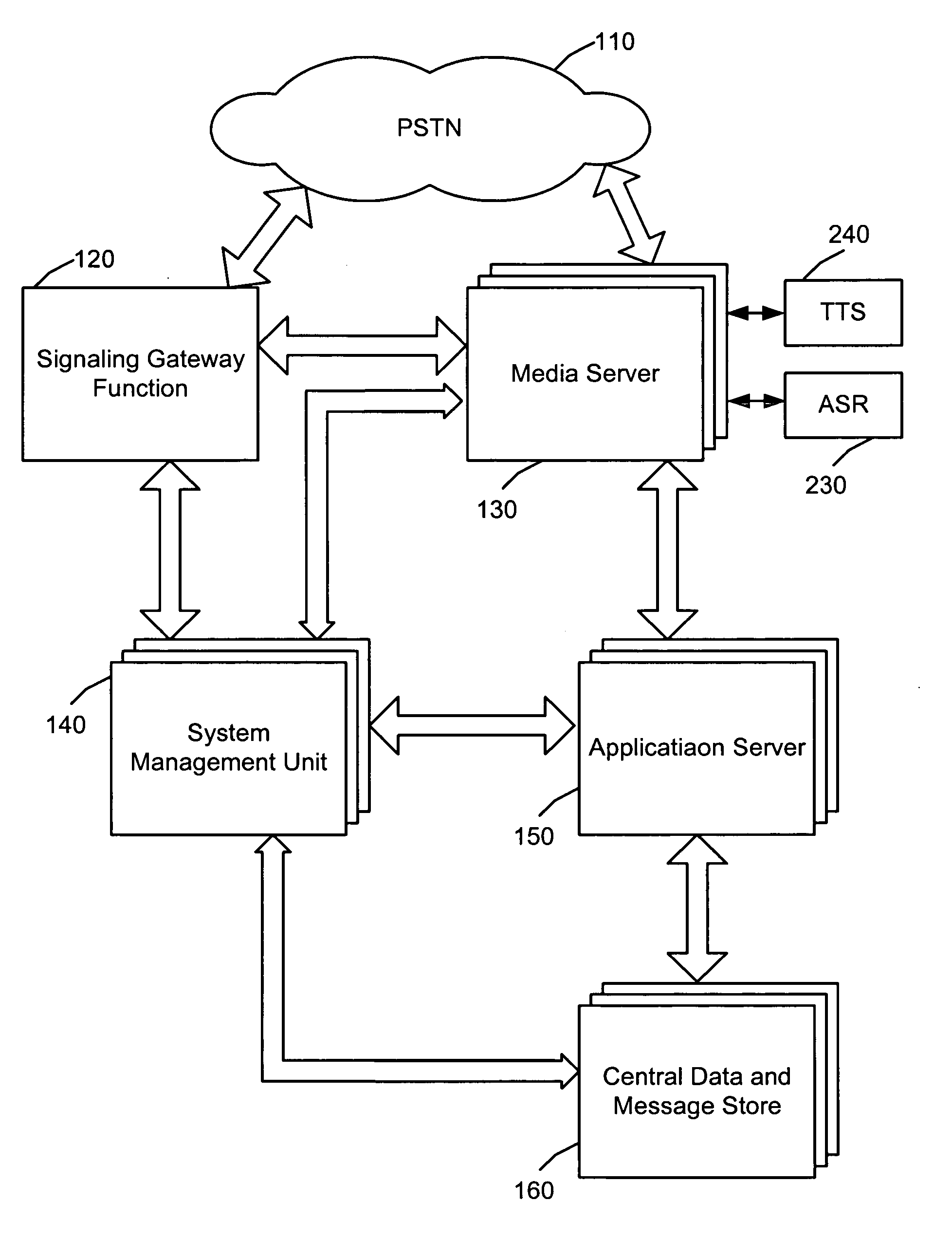
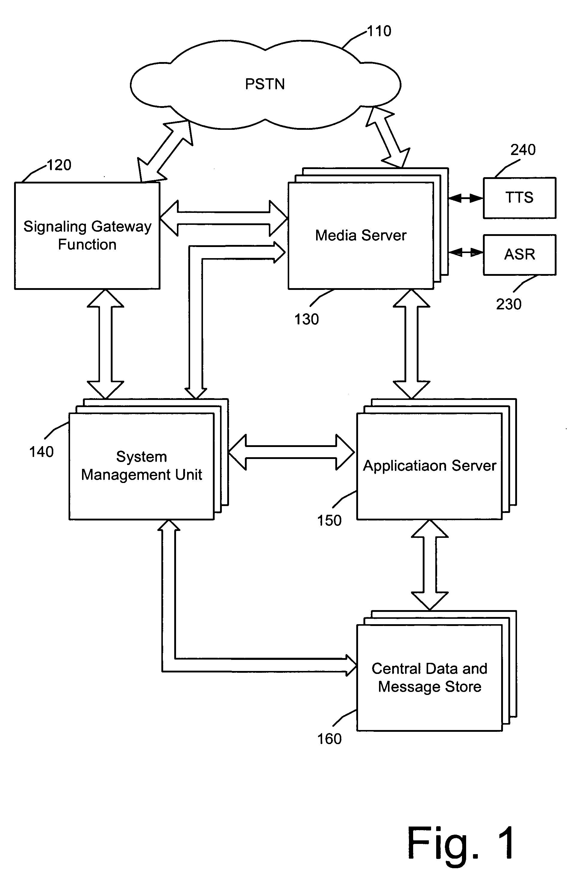
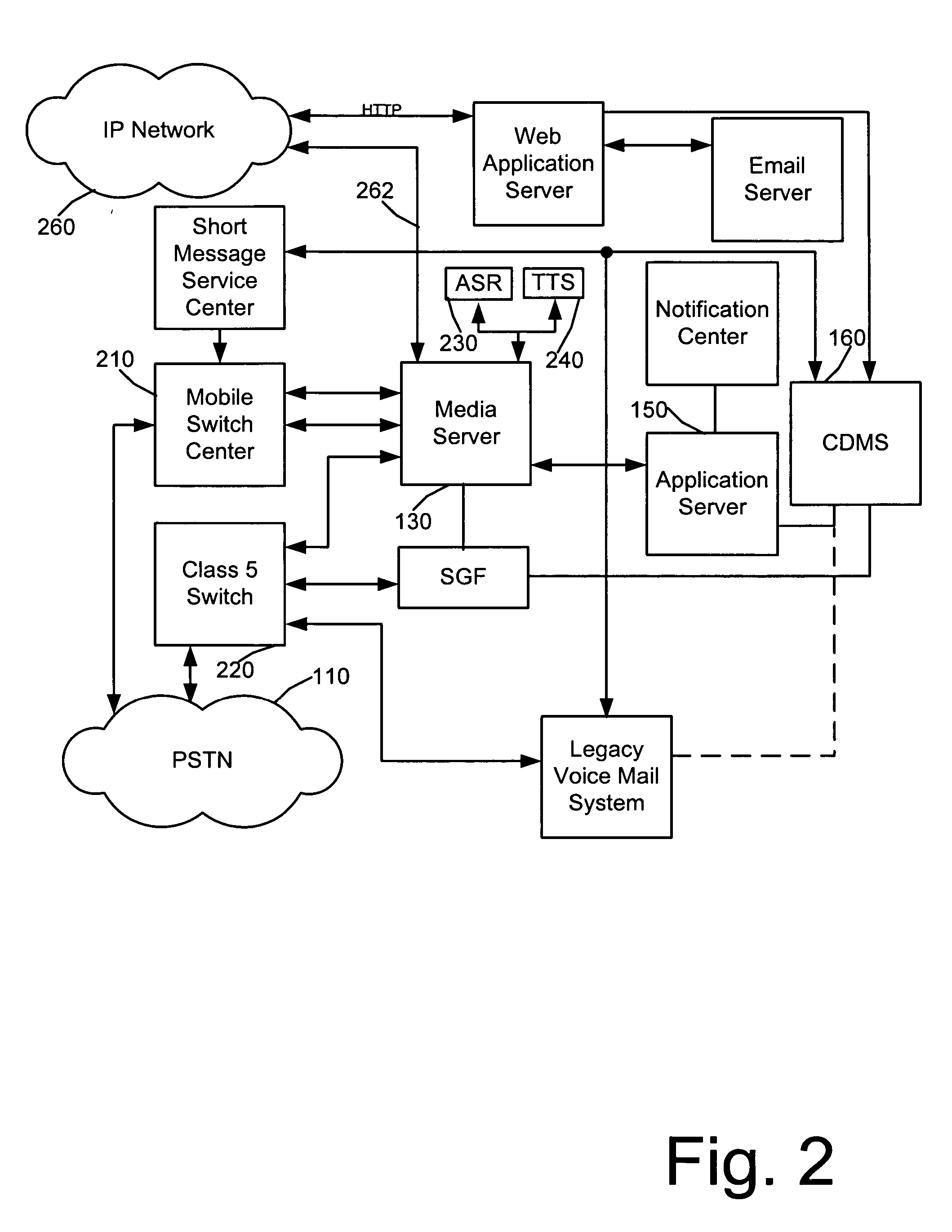
[0020] The present invention provides a distributed IP architecture, also described as a next-generation communications platform, for telecommunications equipment, such as a PBX, voicemail system, or the like. By utilizing the architecture of the present invention, the various functionalities of the telecommunications equipment can be divided amongst various physical components and the physical components can be geographically dispersed. Each of the components communicates with each other, as needed, through independent interfaces to an IP network. The complexities of interfacing to the telephone network are handled through a single gateway component and a simplified protocol is used for communication between the remaining components of the telecommunications equipment or to the telephone network through the gateway component.

[0021] Now turning to the drawings, in which like labels refer to like elements throughout the several views, various aspects and features of the present inve...


PUM


Abstract

A telephone system architecture enabling various components of a telephone system to be distributed geographically yet operates as a seamlessly integrated system. A signaling gateway interfaces to the PSTN and through an SS7 interface. The signaling gateway includes a telephony protocol server. At least one other component of the telephone system includes a telephony protocol client. The telephony protocol client and telephony protocol server communicate over an Internet Protocol (IP) network. The telephony protocol server provides access to the PSTN to the component having the telephony protocol client. Any functions in the various components that require an SS7 interface to the PSTN are simply handled through the signaling gateway by the telephony protocol server.

Description

CROSS-REFERENCE TO RELATED APPLICATIONS [0001] This application claims the benefit of the filing date of United States Provisional Application for Patent entitled DISTRIBUTED IP ARCHITECTURE FOR TELECOMMUNICATIONS SYSTEM, filed on Jun. 30, 2004 and assigned Ser. No. 60 / 584,117.STATEMENT REGARDING FEDERALLY SPONSORED RESEARCH OR DEVELOPMENT [0002] Not applicable. REFERENCE TO SEQUENCE LISTING, A TABLE, OR A COMPUTER PROGRAM LISTING COMPACT DISK APPENDIX [0003] Not applicable. BACKGROUND OF THE INVENTION [0004] The present invention relates to distributed IP systems and telecommunication systems and, more particularly, to a multi-functional telecommunications system with geographically dispersible components that interact over a distributed IP architecture. [0005] Over the past several decades, voice mail has continued to expand and establish itself as a key element in the successful operations of most businesses. The typical voice mail system today can take on a variety of forms, inc...

Claims


Application Information

Patent Timeline
IPC IPC(8): H04L12/66
CPCH04L29/06027H04M3/533H04M7/06H04L65/103H04L65/1043H04L65/104H04M7/126H04L65/1101
Inventor BETTIS, SONNY R.LOWMAN, PHILIP L.SPENCER, JAMES H.
Owner GLENAYRE ELECTRONICS INC
Why Eureka
Try Eureka