Wrist support

a joint support and wrist technology, applied in the field of joint support, can solve the problems of hard-shell or rigid beam components, inconvenient adjustment,

Inactive Publication Date: 2006-01-26
NORDT DEVMENT
View PDF30 Cites 89 Cited by
  • Summary
  • Abstract
  • Description
  • Claims
  • Application Information

AI Technical Summary

Benefits of technology

[0004] A first aspect of the invention generally relates to a joint support and, more particularly, to a wrist support having a first section for receiving a forearm, a second section for receiving a hand, and a bridging section extending between and connecting together the first section and second section. The bridging section is integrally formed in a molding step with at least a portion the first se...

Problems solved by technology

Typical such supports, having hard-shell or rigid beam components, are not conv...

Method used


Image

  • Wrist support
  • Wrist support
  • Wrist support

Examples


first embodiment

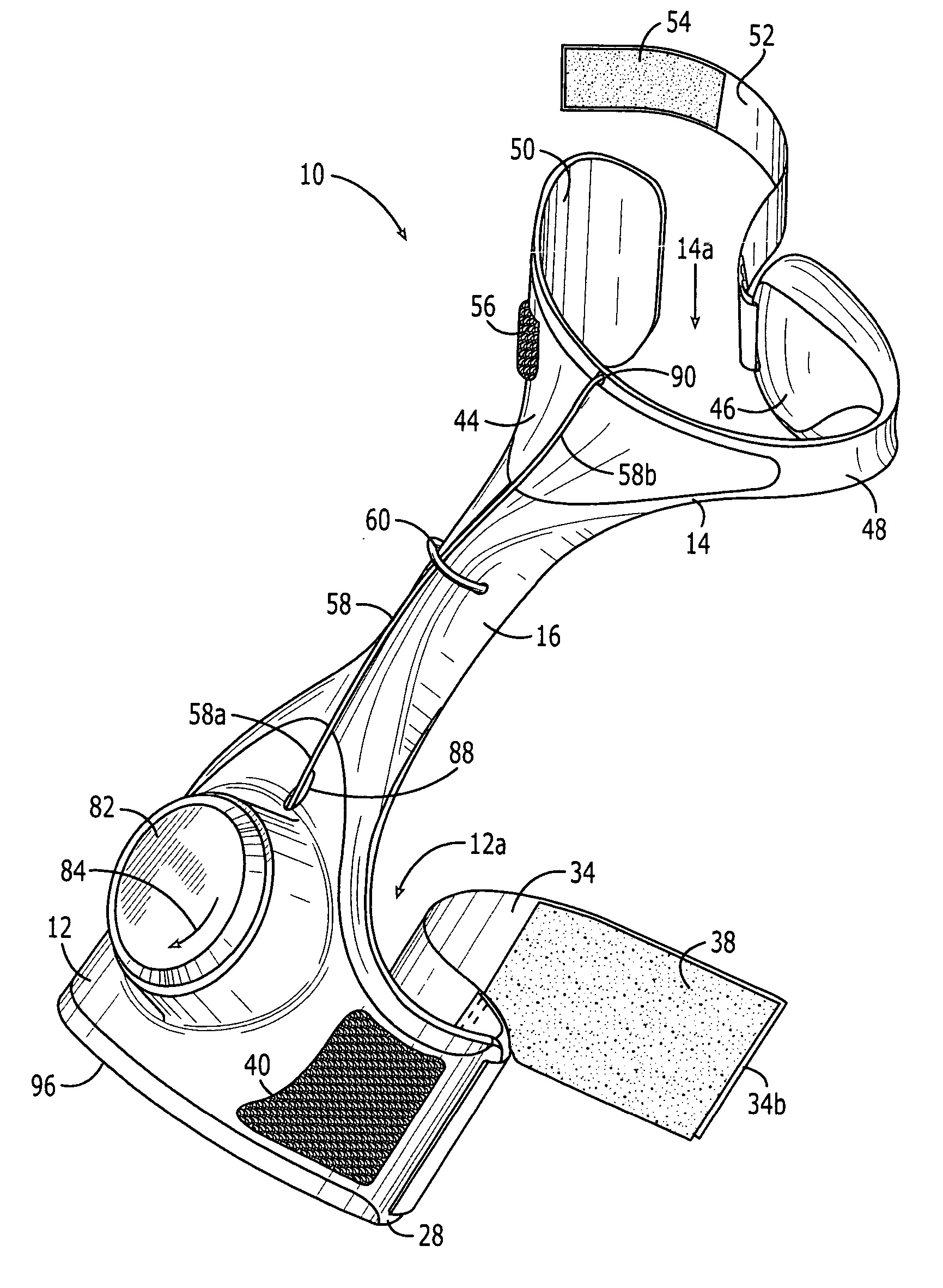
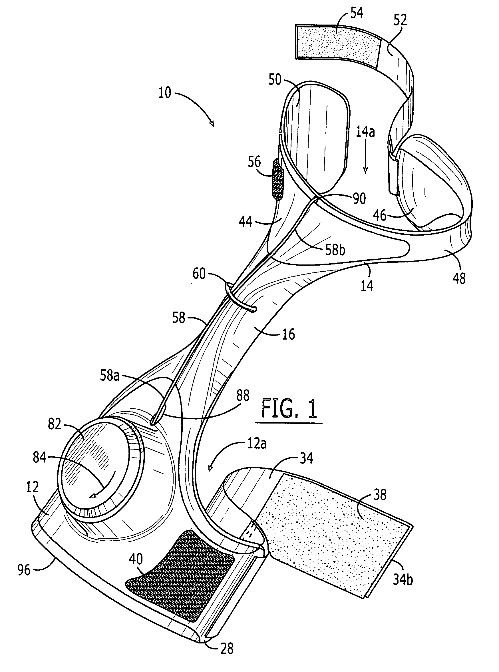
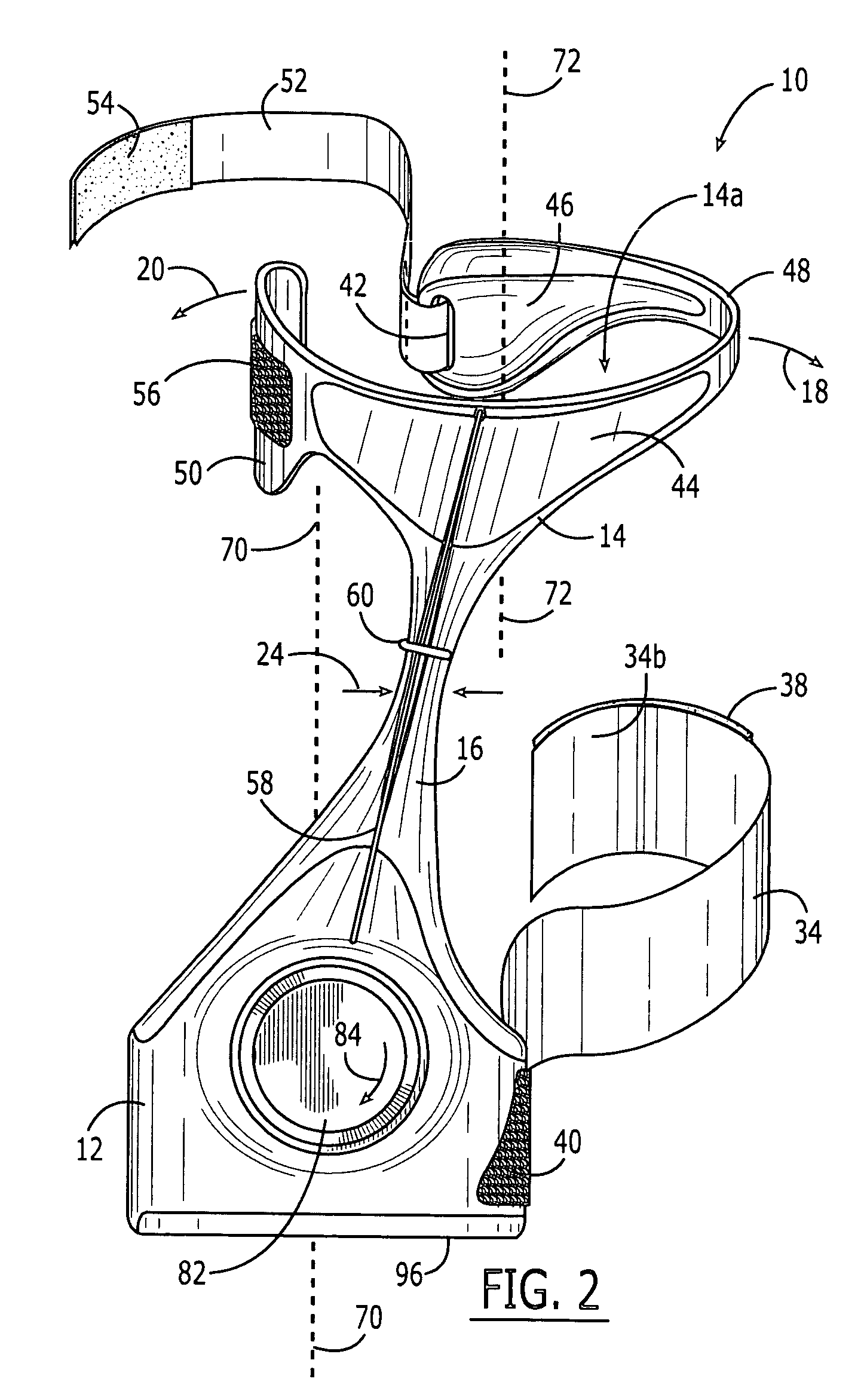
[0027] Turning now the figures, the invention is shown in FIGS. 1-4, wherein a wrist support 10 comprises a first section 12 for receiving a forearm, a second section 14 for receiving a hand, and a bridging section 16 extending between and connecting together the first section 12 and the second section 14. The bridging section 16 permits flexing of the second section 14 relative to the first section 12, particularly in a radial-ulnar plane. That is, the bridging section 16 permits flexing of the second section 14 in a radial direction 18 (FIG. 2) and in an ulnar direction 20 relative to the first section 12.

[0028] The bridging section 16 preferably comprises an elastomeric material that is generally flexible and recoverable. The bridging section 16 generally maintains or biases the second section 14 to obtain a particular disposition, for example that of FIGS. 2-3, relative to the first section 12. However, when forces in radial and ulnar directions 18,20 are present, such as when t...

second embodiment

[0060] Turning now to a second embodiment shown in various views in FIGS. 5-8, a wrist support 110 comprises a first section 112 for receiving a forearm, a second section 114 for receiving a hand, and a bridging section 116 extending between and connecting together the first section and second section. The bridging section 116 permits flexing of the second section 114 relative to the first section 112, particularly in a radial-ulnar plane. That is, the bridging section 116 permits flexing of the second section 114 in a radial direction 118 (FIG. 6) and in an ulnar direction 120 relative to the first section 112.

[0061] The bridging section 116 preferably comprises an elastomeric material that is generally flexible and recoverable. The bridging section 116 generally maintains or biases the second section 114 to obtain a particular disposition, for example that of FIGS. 6-7, relative to the first section 112. However, when forces in radial and ulnar directions 118,120 are present, such...


PUM


Abstract

A wrist support includes a first section for receiving a forearm, a second section for receiving a hand, and a bridging section spanning a wrist and connecting the first and second sections together. The bridging section is integrally formed with some portion of the first section or second section. The disposition of the second section relative to the first section is variable, for example, according to the tension in a tensioning line, wherein the tension may be adjusted by a rotary device.

Description

CROSS-REFERENCE TO RELATED APPLICATIONS [0001] The present application is a continuation-in-part nonprovisional utility patent application of, and claims the benefit of priority under 35 U.S.C. § 120 to, U.S. design patent application Ser. No. 29 / 209,985, filed Jul. 22, 2004, which is incorporated herein by reference; the present application also is a nonprovisional patent application of, and claims the benefit of priority under 35 U.S.C § 119(e) to, U.S. provisional patent application Ser. No. 60 / 590,941, filed Jul. 22, 2004, which is incorporated herein by reference.COPYRIGHT STATEMENT [0002] All of the material in this patent document is subject to copyright protection under the copyright laws of the United States and other countries. The copyright owner has no objection to the facsimile reproduction by anyone of the patent document or the patent disclosure, as it appears in official governmental records but, otherwise, all other copyright rights whatsoever are reserved. BACKGROU...

Claims


Application Information

Patent Timeline
IPC IPC(8): A41D13/08
CPCA61F5/0118A41D13/088
Inventor NORDT, WILLIAM E. IIIKOVACEVICH, IAN D.DAHLQUIST, KEVIN J.PHILPOTT, TOM J.
Owner NORDT DEVMENT
Why Eureka
Try Eureka