
Shifter having neutral lock

a technology of neutral lock and shifter, which is applied in the direction of mechanical control devices, process and machine control, instruments, etc., can solve the problems of relatively expensive and relatively expensive shifter assembly

Inactive Publication Date: 2006-01-26
GRAND HAVEN STAMPED PRODS DIV OF JSJ
View PDF44 Cites 68 Cited by
  • Summary
  • Abstract
  • Description
  • Claims
  • Application Information

AI Technical Summary

Benefits of technology

[0003] One aspect of the present invention is a shifter for controlling a transmission of a vehicle. The shifter includes a base structure and a shift lever that is movably mounted to the base structure for movement between a plurality of control positions. At least one of the control positions comprises a NEUTRAL position. The shifter further includes a shift gate having a plurality of notches corresponding to the control positions. The shift gate is positioned on a selected one of the base and the shift lever. The shifter further includes a movable pawl member selectively engaging the notches of the shift gate to restrict movement of the shift lever relative to the base structure. The pawl member is biased into engagement with th

Problems solved by technology

One problem with this design is that solenoids are relatively expensive, and including two solenoids in a shifter results in a relatively expensive shifter assembly.

Method used


Image

  • Shifter having neutral lock
  • Shifter having neutral lock
  • Shifter having neutral lock

Examples


Embodiment Construction

[0020] For purposes of description herein, the terms “upper,”“lower,”“right,”“left,”“rear,”“front,”“vertical,”“horizontal,” and derivatives thereof shall relate to the invention as oriented in FIG. 1. However, it is to be understood that the invention may assume various alternative orientations and step sequences, except where expressly specified to the contrary. It is also to be understood that the specific devices and processes illustrated in the attached drawings and described in the following specification are simply exemplary embodiments of the inventive concepts defined in the appended claims. Hence, specific dimensions and other physical characteristics relating to the embodiments disclosed herein are not to be considered as limiting, unless the claims expressly state otherwise.

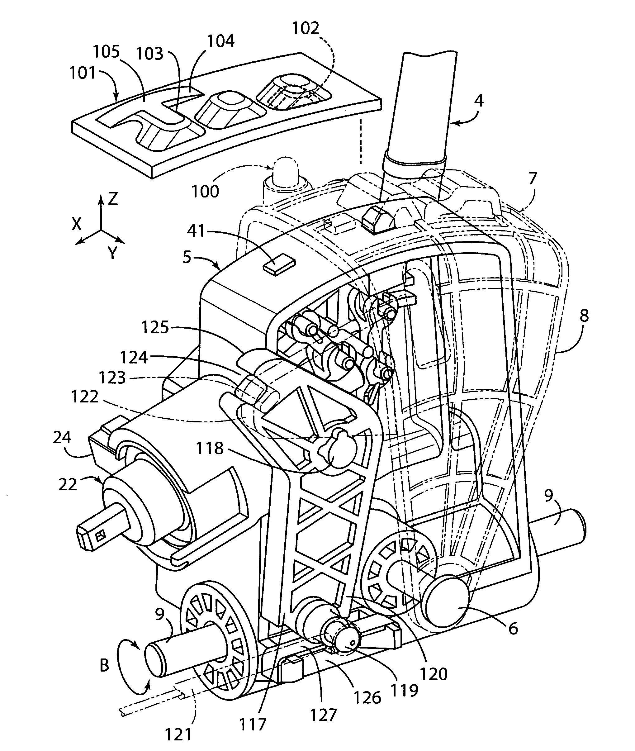
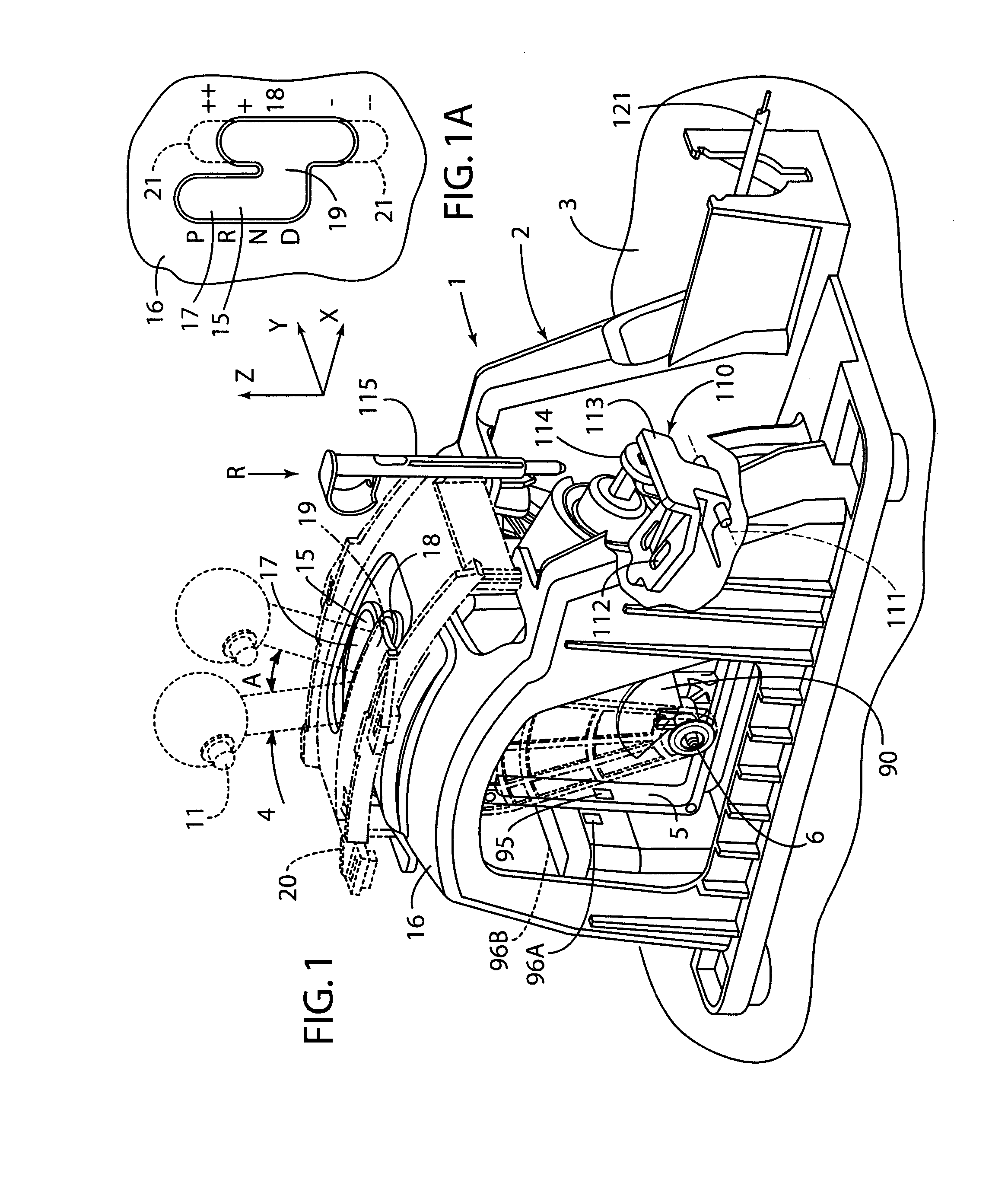
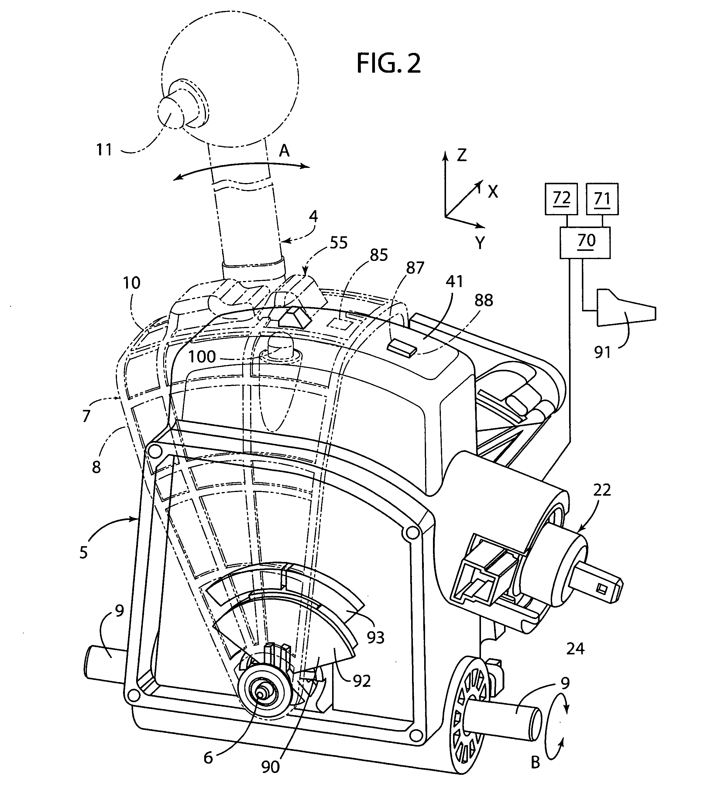
[0021] A shifter 1 according to one aspect of the present invention includes a base structure 2 (FIG. 1) that is configured to secure the shifter 1 to a vehicle structure 3. A shift lever 4 includes a...


PUM


Abstract

A shifter for controlling a transmission of a motor vehicle includes a base structure and a shift lever that is movably mounted to the base structure for movement between a plurality of control positions. At least one of the control positions comprises a NEUTRAL position. The shifter further includes a shift gate having a plurality of notches corresponding to the control positions. The shift gate is positioned on a selected one of the base and the shift lever. The shifter further includes a movable pawl member selectively engaging the notches of the shift gate to restrict movement of the shift lever relative to the base structure. The pawl member is biased into engagement with the shift gate. A movable retaining member selectively engages the shift gate to retain the shift lever in the NEUTRAL position wherein the retaining member is biased out of engagement with the shift gate. The shifter further includes a powered actuator having a movable output member that shifts between a first position, a second position, and a third position. The movable output member operably engages the movable retaining member when in the first position and shifts the movable retaining member into engagement with the shift gate to retain the shift lever in the NEUTRAL position. The movable output member operably engages the movable pawl member when in the third position, and disengages the movable pawl member from the shift gate.

Description

CROSS-REFERENCE TO RELATED APPLICATIONS [0001] The present application claims the benefit of U.S. Provisional Application No. 60 / 591,012, filed Jul. 26, 2004, entitled VEHICLE SHIFTER WITH POWERED PAWL HAVING NEUTRAL LOCK, the entire contents of which are incorporated herein by reference.BACKGROUND OF THE INVENTION [0002] The present invention relates to shifters for transmissions of passenger vehicles, and more particularly relates to shifters having devices to control movement of the shift lever between gear positions. Modern vehicle shifters may be specified or proposed to include neutral lock devices to prevent the shifters from being accidentally shifted from a neutral gear position into a reverse or forward gear position unless the vehicle is traveling at below a predetermined speed, and the brake pedal is depressed. Proposals for neutral lock devices include a second solenoid that may be similar to a park lock solenoid. The second solenoid has an extendable pin that can be ex...

Claims


Application Information

Patent Timeline
IPC IPC(8): B60K20/00G05G5/00
CPCF16H59/0204F16H59/10Y10T74/20085Y10T74/20098F16H61/22
Inventor GROSSMAN, PATRICK S.DE JONGE, ROBERT A.
Owner GRAND HAVEN STAMPED PRODS DIV OF JSJ
Learn More