Image forming apparatus

Inactive Publication Date: 2006-01-26
SHARP KK
View PDF1 Cites 16 Cited by
  • Summary
  • Abstract
  • Description
  • Claims
  • Application Information

AI Technical Summary

Benefits of technology

[0008] According to the invention, an image forming apparatus includes an original scanning section, an image forming section and a sheet feeding section which are disposed in this order from top to bottom. The image forming section has a smaller cross-sectional area when cut by a horizontal plane than the original scanning section and the sheet feeding section in order that a sheet receiving section into which eac

Problems solved by technology

This kind of image forming apparatus requires a relatively large space for installation since not only a space for the housing but also a space for the sheet receiving section are needed.
The front access type sheet receiving section however has a problem that the sheets ejected to the sheet receiving section are difficult to see from a distance.
For this reason, it is occasionally difficult for a user who has entered an image forming command from a place distant from

Method used


Image

  • Image forming apparatus
  • Image forming apparatus
  • Image forming apparatus

Examples


Embodiment Construction

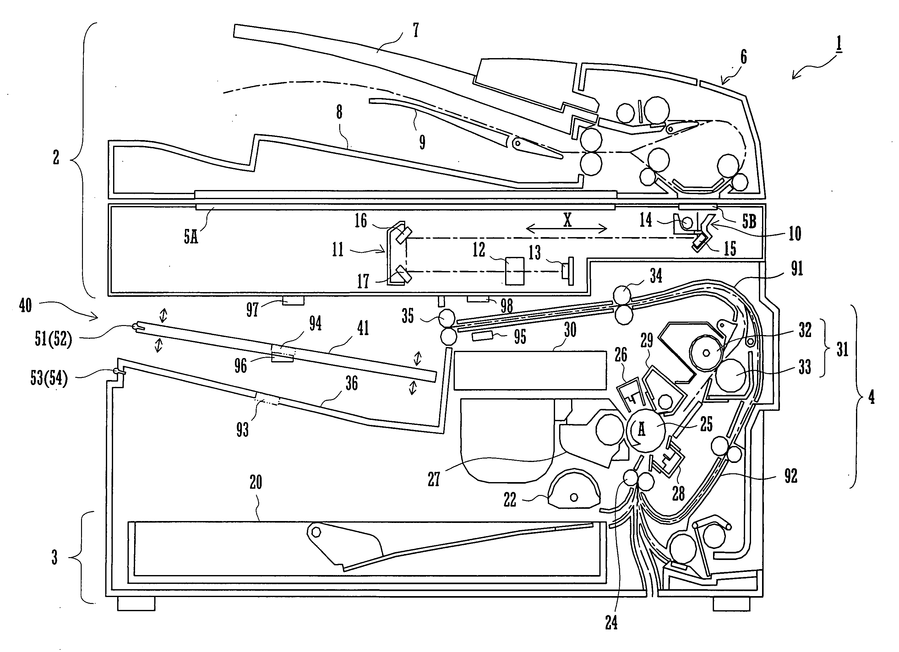
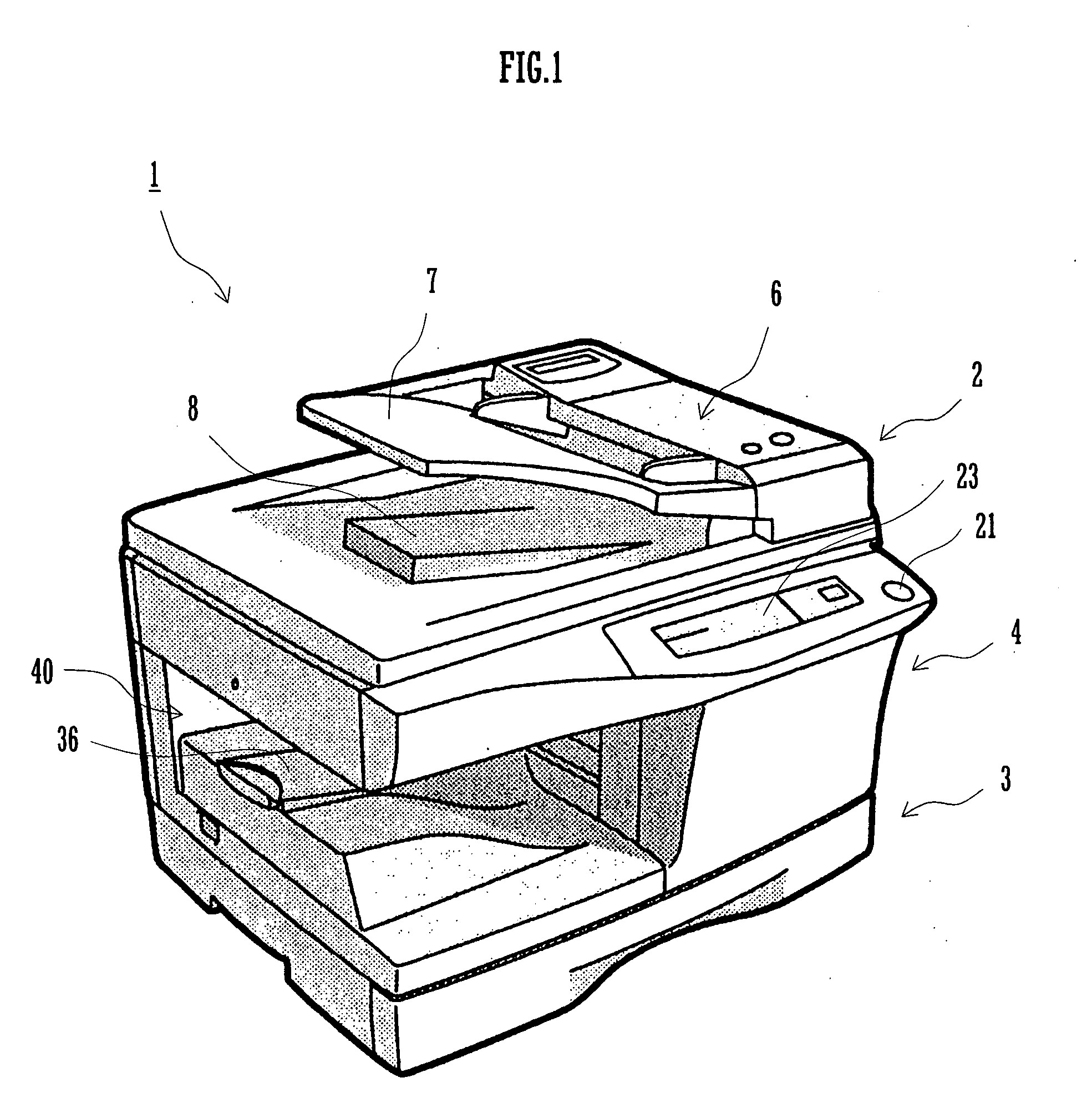
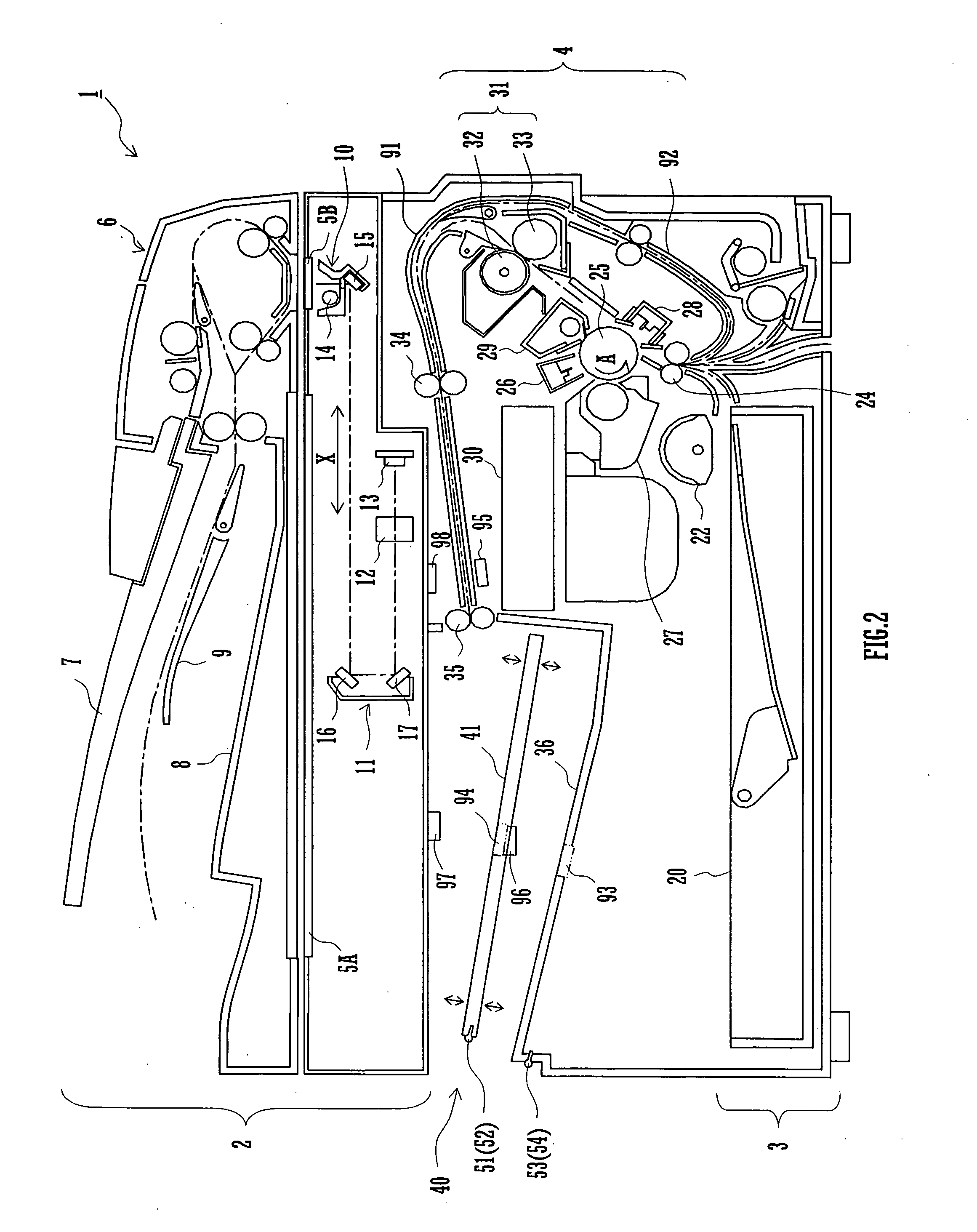
[0015]FIG. 1 is a perspective view of an image forming apparatus 1 according to a preferred embodiment of the invention. As shown in FIG. 1, the image forming apparatus 1 includes an original scanning section 2, a sheet feeding section 3, an image forming section 4 and a sheet receiving section 40. The original scanning section 2 is disposed at an upper part of the image forming apparatus 1 while the sheet feeding section 3 is disposed at a bottom part of the image forming apparatus 1. The image forming section 4 is disposed between the original scanning section 2 and the sheet feeding section 3, so as to be sandwiched therebetween. The image forming section 4 is structured to have a small cross-sectional area when cut by a horizontal plane as compared to the original scanning section 2 and the sheet feeding section 3. Thus, there is formed a sheet receiving space surrounded by the original scanning section 2, the sheet feeding section 3 and the image forming section 4, and sheets e...


PUM


Abstract

An image forming apparatus includes an original scanning section, a sheet feeding section, an image forming section, a sheet receiving section and an indicator (LEDs). The image forming section is located between the original scanning section and the sheet feeding section and has a smaller cross-sectional area when cut by a horizontal plane than either of the original scanning section and the sheet feeding section such that a sheet receiving space into which each sheet of the printing medium is ejected is left between the original scanning section and the sheet feeding section. The sheet receiving section is located in the sheet receiving space for receiving the sheets of the printing medium ejected from the image forming section. The indicator notifies users that one or more sheets of the printing medium have been delivered to the sheet receiving section by emitting light.

Description

CROSS REFERENCE [0001] This Nonprovisional application claims priority under 35 U.S.C. § 119(a) on Patent Application No. 2004-211426 filed in Japan on Jul. 20, 2005, the entire contents of which are hereby incorporated by reference. BACKGROUND OF THE INVENTION [0002] The present invention relates generally to an image forming apparatus for forming an image on a printing medium and, more particularly, the invention pertains to an image forming apparatus which delivers each sheet of a printing medium to a location surrounded by an original scanning section, an image forming section and a sheet feeding section. [0003] Conventionally, most of image forming apparatuses are provided with a sheet receiving section projecting outward from a side surface of a housing. This kind of image forming apparatus requires a relatively large space for installation since not only a space for the housing but also a space for the sheet receiving section are needed. [0004] Japanese Patent Application Lai...

Claims


Application Information

Patent Timeline
IPC IPC(8): G03G15/00
CPCG03G15/6552
Inventor KUBO, TAKASHI
Owner SHARP KK
Why Eureka
Try Eureka