Reciprocating compressor

a compressor and reciprocating technology, applied in the direction of positive displacement liquid engine, piston pump, dynamo-electric machine, etc., can solve the problems of repetitive process sequence, increased number of components, complicated assembly process, etc., and achieve the effect of reducing the number of components and improving workability

Inactive Publication Date: 2006-01-26
LG ELECTRONICS INC
View PDF3 Cites 60 Cited by
  • Summary
  • Abstract
  • Description
  • Claims
  • Application Information

AI Technical Summary

Benefits of technology

[0015] Therefore, an object of the present invention is to provide a reciprocating compressor capable of reducing the number of co

Problems solved by technology

And, such a series of processes are repetitively performed.
However, the conventional reciprocating compressor having such a structure is disadvantageous in that its assembly processes are complicated because the mover 33 is disposed between the outer stator 31 and the

Method used


Image

  • Reciprocating compressor
  • Reciprocating compressor
  • Reciprocating compressor

Examples


Embodiment Construction

[0029] Reference will now be made in detail to the preferred embodiments of the present invention, examples of which are illustrated in the accompanying drawings.

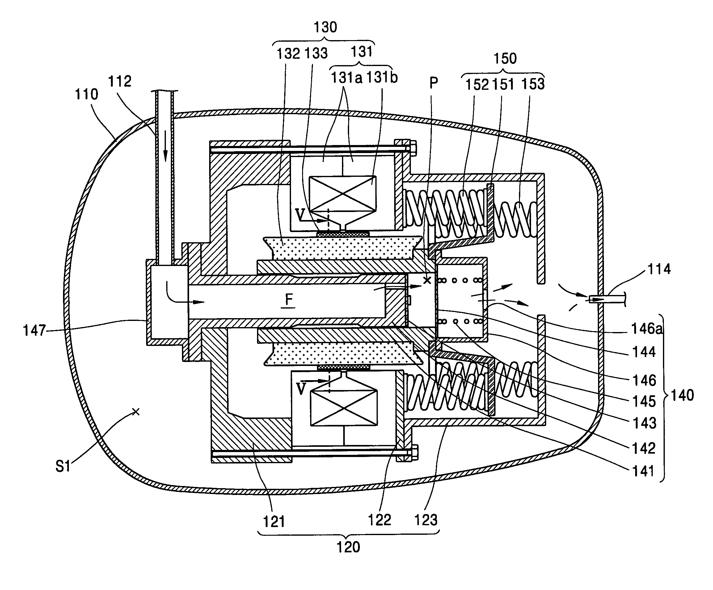
[0030] As shown in FIG. 4, a reciprocating compressor in accordance with the present invention includes: a casing 110 provided with a gas suction pipe 112 and a gas discharge pipe 114; a reciprocating motor 130 disposed inside the casing 110, for generating a driving force; a compression unit 140 for sucking, compressing and discharging a gas by the driving force of the reciprocating motor 130; a resonant spring unit 150 for providing a resonant motion to a reciprocating motion generated at the reciprocating motor 130; and a frame unit 120 for supporting the reciprocating motor 130, the compression unit 140 and the resonant spring unit 150.

[0031] The gas suction pipe 112 directly communicates with the compression unit 140, and the gas discharge pipe114 communicates with an internal space of the casing 110. Accordingly, th...


PUM


Abstract

A reciprocating compressor includes: a cylinder installed inside a casing and having a space therein; a piston disposed inside the cylinder; an inner stator fixed at an outer circumference of the cylinder; a magnet fixed at an outer circumference of the inner stator; and an outer stator disposed to maintain a certain distance from an outer circumference of the magnet. Accordingly, the number of components is reduced thus to reduce a manufacturing cost, and performance can be also improved.

Description

BACKGROUND OF THE INVENTION [0001] 1. Field of the Invention [0002] The present invention relates to a reciprocating compressor, and particularly, to a reciprocating compressor in which a stator and a magnet are fixed to a cylinder and the cylinder is moved. [0003] 2. Description of the Background Art [0004] In general, a reciprocating compressor is an apparatus for sucking, compressing and discharging a gas as a piston linearly reciprocates in a cylinder. [0005] As shown in FIG. 1, a conventional reciprocating compressor includes: a casing 10 provided with a gas suction pipe 12 and a gas discharge pipe 14; a reciprocating motor 30 disposed inside the casing 10, for generating a driving force; a compression unit 40 for sucking, compressing and discharging a gas by the driving force of the reciprocating motor 30; a resonant spring unit 50 for providing a resonant motion to the reciprocating motion of the reciprocating motor 30; and a frame unit 20 for supporting the reciprocating mot...

Claims


Application Information

Patent Timeline
IPC IPC(8): F04B35/04F04B17/04
CPCF04B35/045Y10S417/902F04B17/04
Inventor SONG, GYE-YOUNGKIM, KWANG-WOOKKANG, JE-NAM
Owner LG ELECTRONICS INC
Why Eureka
Try Eureka