Multi-band antenna

a multi-band antenna and antenna technology, applied in the field of antennas, can solve the problems of reducing the aesthetic and aerodynamic impact of these antennas, and not being suitable for multi-operation, and achieve the effect of convenient reception

Inactive Publication Date: 2006-02-02
CHIANG KUO CHING
View PDF16 Cites 19 Cited by
  • Summary
  • Abstract
  • Description
  • Claims
  • Application Information

AI Technical Summary

Benefits of technology

[0011] The advantage of the invention is the multi-band behavior of the antenna, especially the fractal antenna which allows a convenient reception of single for communication of the vehicle. The multi-band behavior is obtained by a set of geometry patterns of the same dimension. The transparent materials may be formed by sputtering vacuum deposition process. An additional passive layer can be added to protect the conducting layer. Materials for this passivation layer are made, for instance, of oxide, or any other polymeric material, polymer, resin coating on the structure. The method for forming the transparent conductive layer includes ion beam method at low temperature, see 1999, IEEE, 1191. U.S. Pat. No. 6,743,476 disclosed a method of producing thin film electrode at room temperature. Both of the ion beam and sputter is expensive. During the formation process, the present invention suggested that a mask can be placed on the substrate material to obtain the desired multi-band antenna shape. This mask normally is made of conducting material such as stainless steel or copper, or a photosensitive material to create the mask by photochemical processes. Then, the pattern can be “print” on the desired object. Thus, the expensive sputter process can be replaced by the chemical solution coating.
[0012] An antenna system includes a driven element, and at least one element a portion of which is a fractal element selected from a fractal counterpoise element. Wherein the fractal element is superposition over at least N=1 iterations of a fractal generator motif. An iteration is placement of the fractal generator motif upon a base figure through at least one positioning selected from the group consisting of (i) rotation, (ii) stretching, and (iii) translation.

Problems solved by technology

The current tendency in the automotive sector is to reduce the aesthetic and aerodynamic impact due to these antennas by embedding them in the vehicle structure.
Obliviously some of the antenna configurations can only operate at a determinate frequency band in reason of the frequency dependence of the antenna parameter and are not suitable for a multi-operation.

Method used


Image

  • Multi-band antenna
  • Multi-band antenna
  • Multi-band antenna

Examples


Embodiment Construction

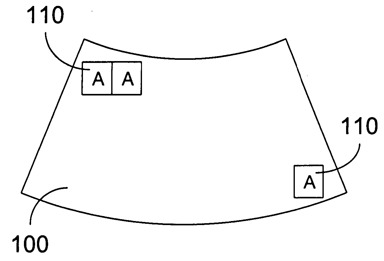
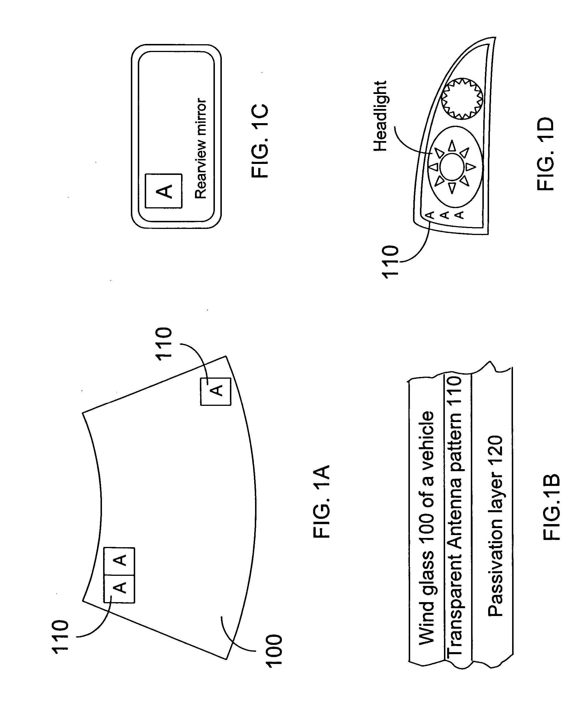
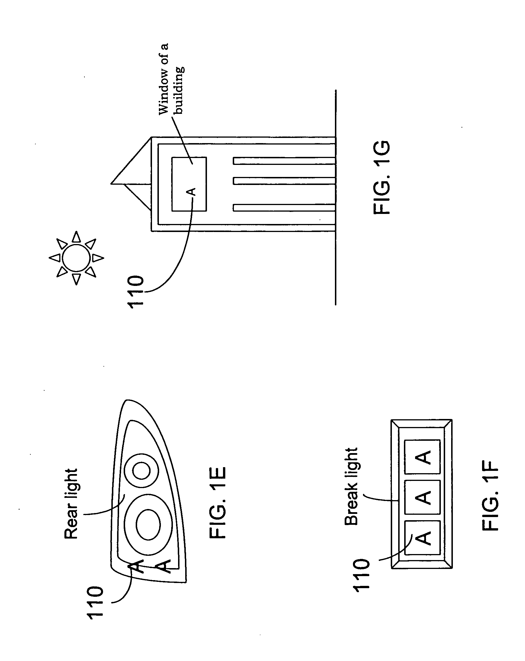
[0026] The present invention describes a multi-band antenna for vehicle or portable device. A configuration of the antenna pattern includes a set of polygonal elements, all of them of the same class (the same number of sides like), wherein the polygonal elements are electromagnetically coupled either by means of an ohmic contact or a capacitive or inductive coupling mechanism. The antenna configuration can be composed by whatever class of polygonal elements (triangle, square, pentagon, hexagon or even a circle or an ellipse in the limit case of infinite number of sides) as long as they are of the same class. The present invention differs from a conventional shape and the material to form the antenna. The antenna structure is easily identifiable and distinguished from a conventional structure by identifying the majority of elements and the material which constitute it. The main advantage addressed by fractal-shaped antennas antenna were a multi-frequency behavior, that is the antenna...


PUM

PropertyMeasurementUnit
radiusaaaaaaaaaa
widthaaaaaaaaaa
widthaaaaaaaaaa

Abstract

The present invention discloses a multi-band antenna, especially the fractal antenna which allows a convenient reception of single for communication. The multi-band behavior is obtained by a set of geometry patterns of the same basic elements. The materials of the antenna may be formed by chemical solution or sputtering vacuum deposition process. An additional passive layer can be added to protect the conducting layer of the antenna. Materials for this passivation layer are made, for instance, of oxide, or any other polymeric material, polymer, resin coating on the structure.

Description

FIELD OF THE INVENTION [0001] The present invention relates an antenna, and more particularly, a multi-band transparent antenna coated on an object. BACKGROUND OF THE INVENTION [0002] Recently, the wireless telecommunication is wide spread in the world. Most of the wireless devices such as portable phone, personal assistance and digital television need the receiving apparatus to receive the transmission signal. Owing to digitization of information signals, various types of information such as audio information, image information, etc. can be easily handled on personal computers, mobile devices, etc. Audio and image codec technologies are used to promote the band compression of these types of information. The digital communication and the digital broadcasting are creating an environment to easily and efficiently deliver such information to various communication terminal devices. For example, audio video data (AV data) can be received on a portable telephone. [0003] The wireless commu...

Claims


Application Information

Patent Timeline
Patent Type & Authority Applications(United States)
IPC IPC(8): H01Q1/32
CPCH01Q1/1271H01Q1/325Y10T29/49016H01Q1/36H01Q1/3266
Inventor CHIANG, KUO CHING
Owner CHIANG KUO CHING
Why Eureka
Try Eureka