Ink jet printer head assembly

a printer head and assembly technology, applied in the direction of printing, other printing apparatus, etc., can solve the problems of inability to break up the ink stream into suitable droplets, potential leakage and pressure loss, and increase the risk of damage to the ink jet, so as to facilitate the maintenance of parts and quick repair of parts

Active Publication Date: 2010-09-23
VIDEOJET TECH INC
View PDF10 Cites 5 Cited by
  • Summary
  • Abstract
  • Description
  • Claims
  • Application Information

AI Technical Summary

Benefits of technology

[0010]Given that continuous ink jet printers are typically used on production lines for long uninterrupted periods, reliability of parts, rapidity of repair of parts and ease of maintenance of parts may be important issues.

Problems solved by technology

If the ink is too viscous, because its temperature is too low, or too thin, because it is too hot, then the ink stream will not break up into suitable droplets.
As the ink circulates through the system, there is a tendency for it to thicken as a result of solvent evaporation, particularly in relation to the recirculated ink that has been exposed to air in its passage between the nozzle and the gutter.
The many connections between the components and the conduits within the print head assembly all represent a potential source of leakage and loss of pressure.
Moreover, the complexity and compactness of the print head assembly mean that when a component in the print head assembly fails, it is generally necessary to retire the print head assembly and either send it for repair or scrap and replace it, whilst an entire replacement print head assembly may have to be used to ensure continuity of production.
On-site repairs would not be feasible, as the presence of multiple conduits and components in the interior of the print head assembly makes access to certain components difficult in the event of servicing or repair.
Given that continuous ink jet printers are typically used on production lines for long uninterrupted periods, reliability of parts, rapidity of repair of parts and ease of maintenance of parts may be important issues.

Method used


Image

  • Ink jet printer head assembly
  • Ink jet printer head assembly
  • Ink jet printer head assembly

Examples


Embodiment Construction

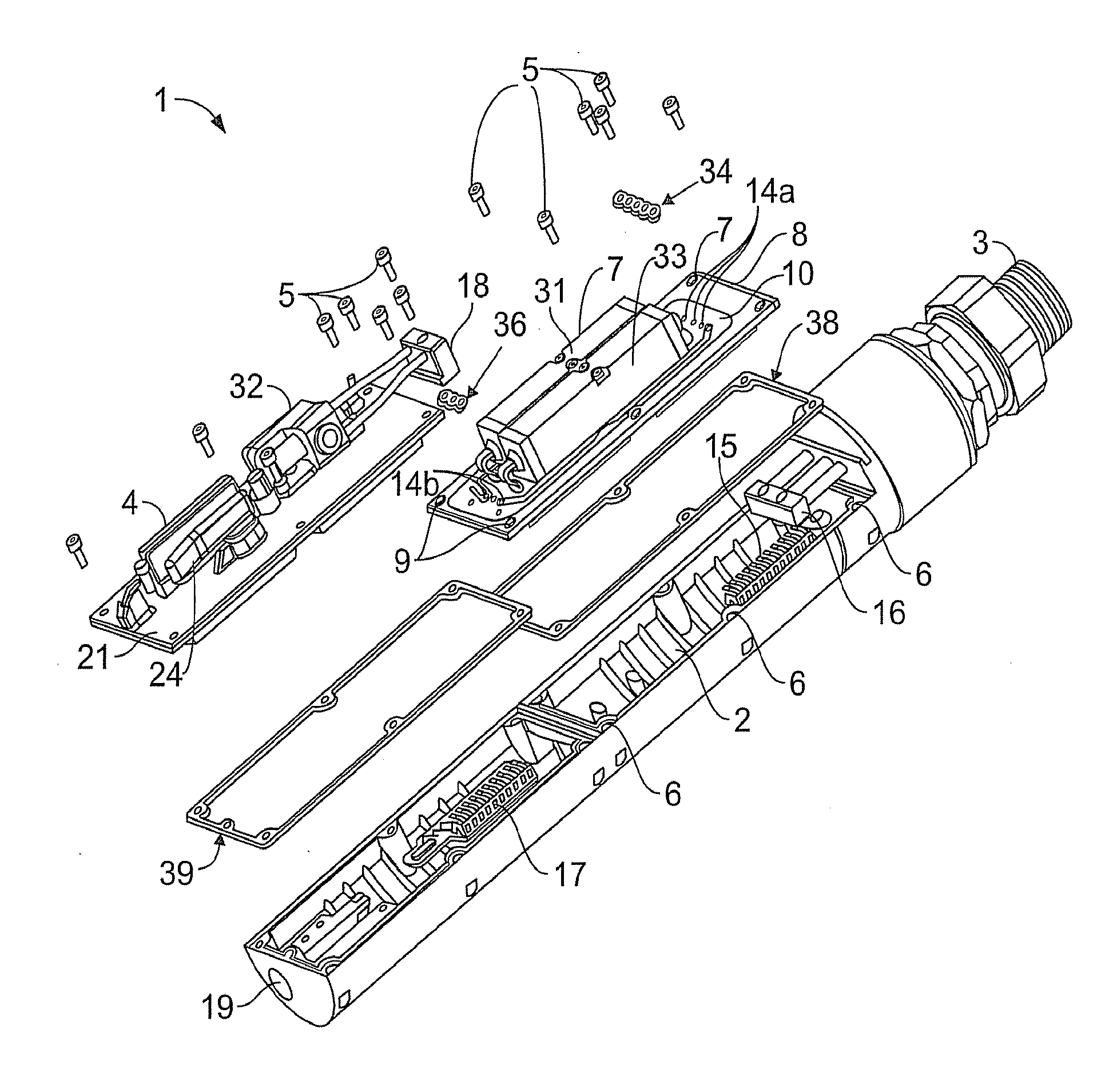
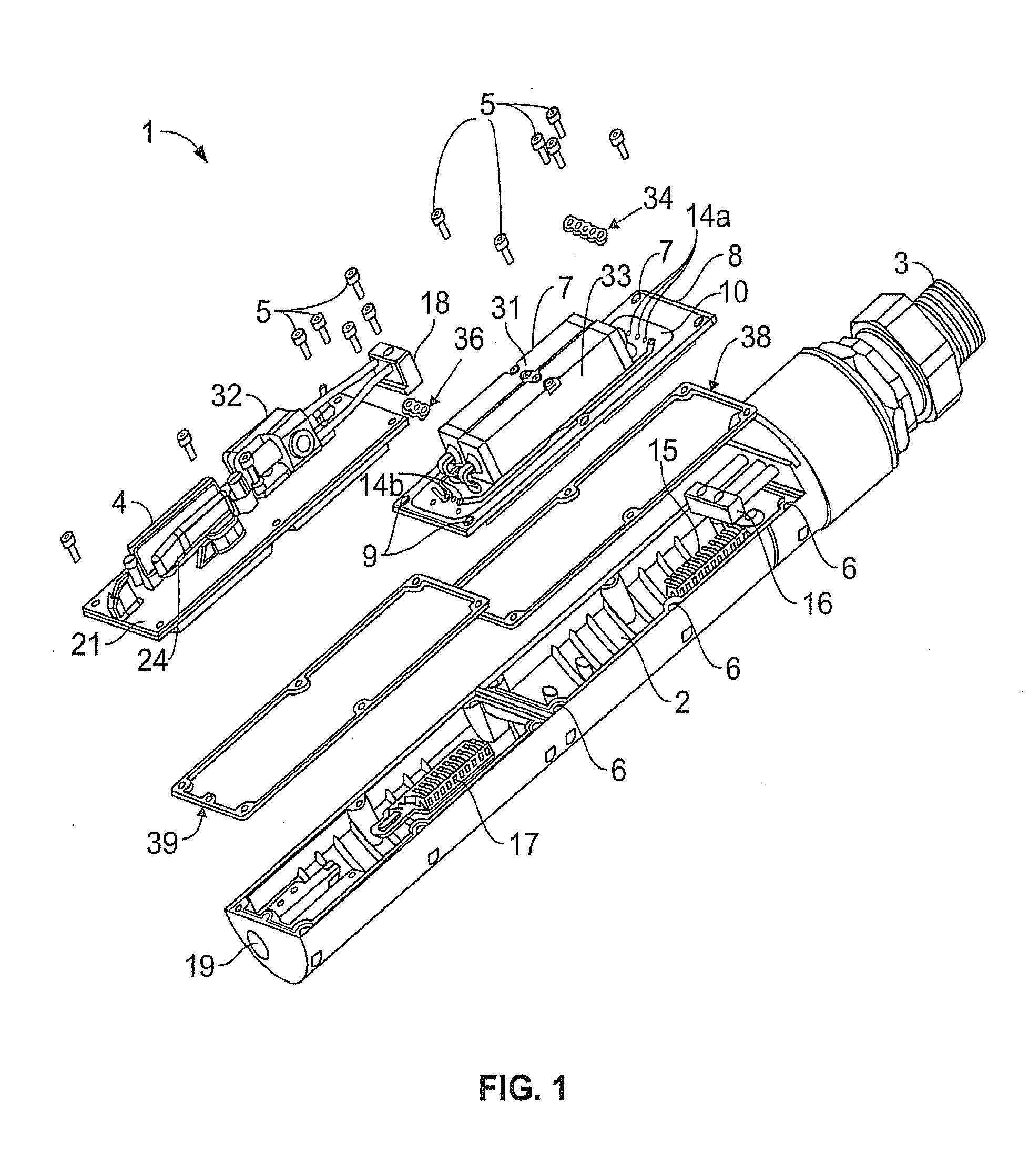
[0045]Referring now to FIG. 1, this shows a print head assembly 1 having a chamber 2 connected to a supply conduit 3 linking the print head assembly 1 to the rest of the printer (not shown). An ink droplet generator module 4 is shown attached to the chamber 2 by bolts 5 mating with tapped holes 6. A seal or gasket 39 may be disposed between ink droplet generator module 4 and chamber 2. The ink droplet generator 4 module (described in further detail below) may include such elements as a piezoelectric element acting as ink droplet generator, a charge electrode, deflector plates, a phase measurement system, a gutter and an exit region 19 where the droplets are printed.

[0046]A heater module 7 has a plate 8 having holes 9 by means of which it may be attached to the chamber 2 using the bolts 5 in the tapped holes 6. A seal or gasket 38 may be disposed between heater module and chamber 2. A shim 10 is welded to the plate 8 forming a heater module manifold with fluid pathways formed between...


PUM


Abstract

A print head assembly for a continuous ink jet printer has an ink heater module, including a valve assembly, which can be independently attached to or detached from the print head assembly. The print head assembly may also have an ink droplet generator module which is independently replaceable and may have other independently replaceable modules. Fluid pathways for in and solvent in the modules are preferably in the form of manifolds having fluid conduits defined between opposing faces of members of the modules. The modular print head assembly is easily repaired and maintained and the number of connectors prone to fluid leakage is minimized by the manifolds.

Description

[0001]The present invention relates to ink jet printing and more particularly to a print head assembly for an ink jet printer such as a continuous ink jet printer.BACKGROUND[0002]In ink jet printing systems the print is made up individual droplets of ink generated at a nozzle and propelled towards a substrate. There are two principal systems: drop on demand where ink droplets for printing are generated as and when required; and continuous ink jet printing in which droplets are continuously produced and only selected ones are directed towards the substrate, the others being recirculated to an ink supply.[0003]Continuous ink jet printers supply pressurised ink to a print head assembly, which has a heater for raising the temperature of the ink to a controlled temperature and a drop generator where a continuous stream of ink emanating from a nozzle is broken up into individual regular drops by an oscillating piezoelectric element. The drops are directed past a charge electrode where the...

Claims


Application Information

Patent Timeline
Patent Type & Authority Applications(United States)
IPC IPC(8): B41J29/38B41J2/14
CPCB41J2/02B41J2/175B41J2002/14362B41J2/195B41J29/02B41J2/185
Inventor OMER, SALHADINZABA, JERZY
Owner VIDEOJET TECH INC
Why Eureka
Try Eureka