Striking surface of golf club heads

a golf club head and striking surface technology, applied in the field of golf club head striking surface, can solve the problems of awkward appearance of the rough surface and the inability to make grooves on the striking surfa

Inactive Publication Date: 2006-02-02
YAWEI IND
View PDF3 Cites 56 Cited by
  • Summary
  • Abstract
  • Description
  • Claims
  • Application Information

AI Technical Summary

Benefits of technology

[0006] The present invention will become more obvious from the following description when taken in connection with the acco...

Problems solved by technology

However, the chemical-etching results rough surface that is awkward in appearance and cannot make grooves in the striking surface 40.
All of the above men...

Method used


Image

  • Striking surface of golf club heads
  • Striking surface of golf club heads
  • Striking surface of golf club heads

Examples


Embodiment Construction

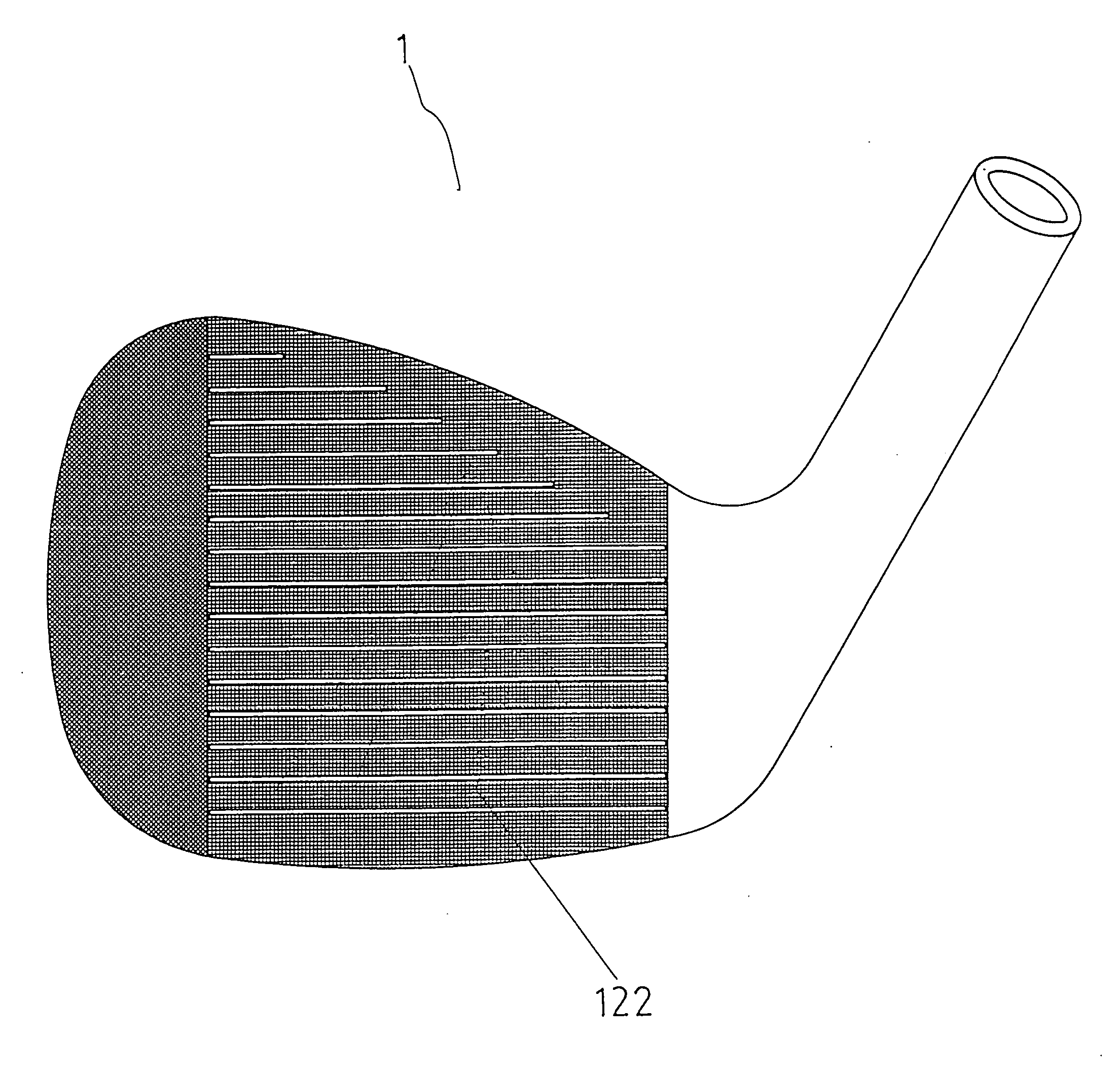
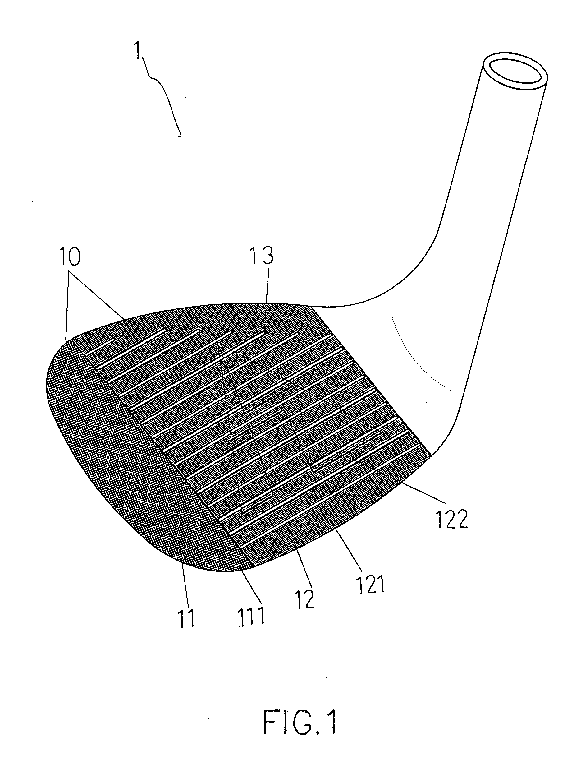
[0013] Referring to FIG. 1, the golf club head 1 of the present invention comprises a striking surface 10 composed of a toe area 11 and striking area 12. The toe area 11 includes cruciform patterns 111 made by CNC and the striking area 12 includes parallel grooves 13 and at least one pattern 121 made by electro-etching. An identification pattern 122 such as a logo made by electro-etching is defined in the striking area 12.

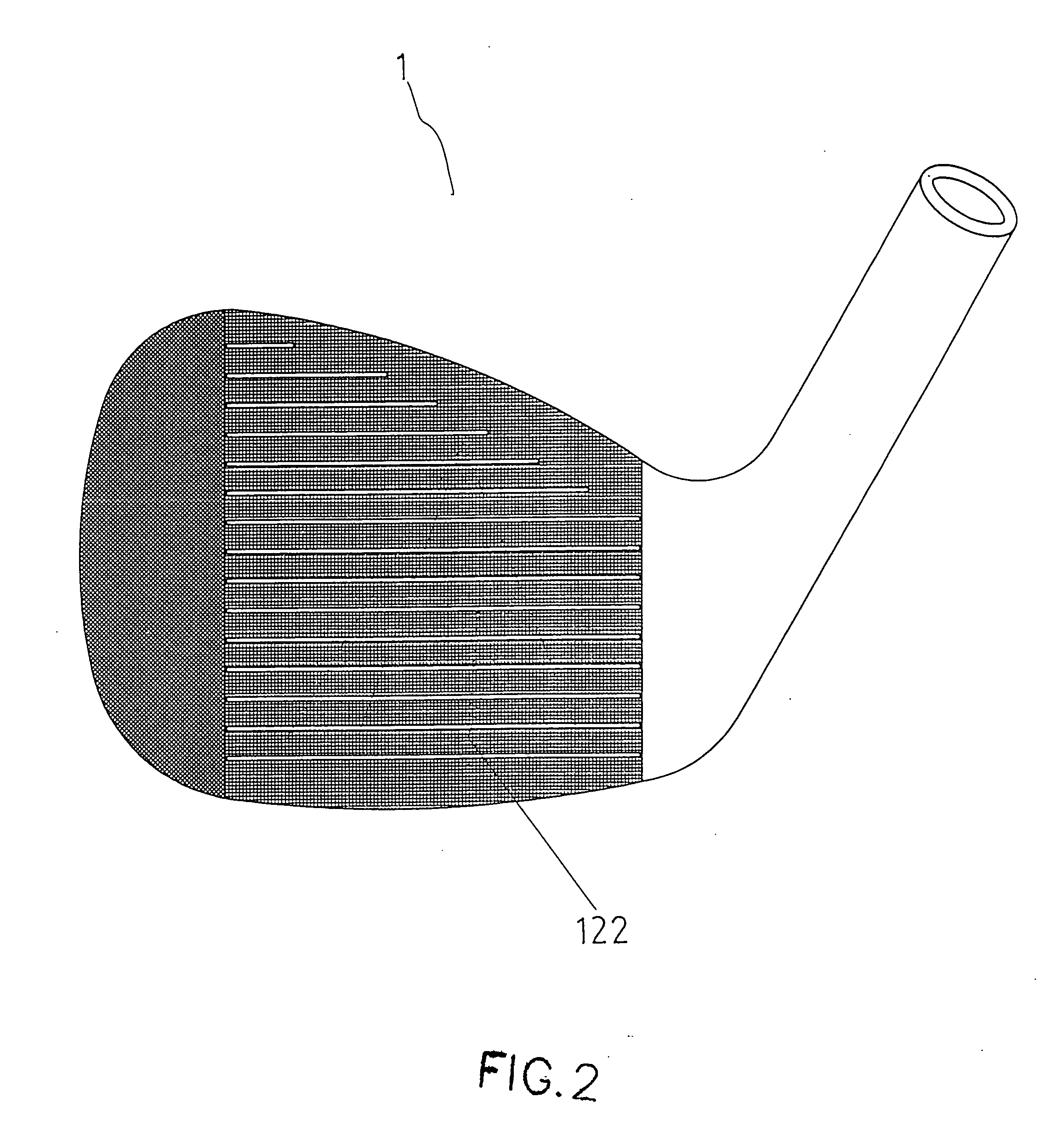
[0014] As shown in FIGS. 2 and 3, the identification pattern 122 is hidden when viewed perpendicularly to the striking surface and is visible when viewed from an angle to the striking surface 10.

[0015] The golf club head 1 requires only one time of machining process such that the manufacturing cost is less than that of the conventional golf club heads. The striking surface 10 made by way of electro-etching provides a non-slippery surface and the golf ball can be delivered to a far distance. The post-rotation of the golf ball is satisfied. The identification patte...


PUM


Abstract

A golf club head includes a striking surface composed of a toe area and striking area. The toe area includes cruciform patterns machined by CNC and the striking area includes parallel grooves and at least one pattern made by electro-etching.

Description

FIELD OF THE INVENTION [0001] The present invention relates to a striking surface of a golf club head and the surface is made with grooves in the surface by way of electro-etching. BACKGROUND OF THE INVENTION [0002] A conventional golf club head 2 is disclosed in FIG. 4, and generally includes a striking surface 20 which is polished first and then processed by way of sand blasting to form a rough surface so as to increase the ball-controlling coefficient. Nevertheless, the rough surface on the surface 20 does not last long. FIG. 5 shows that golf club head 3 can also be made by CNC and the striking surface 30 thereof is then electro-plated with a coating material and processed by heat treatment. This type of striking surface 30 is slippery for the golf ball which cannot be handled properly. FIG. 6 shows that the golf club head 4 is polished and the striking surface 40 is processed by way of chemical-etching, electroplating and heat treatment. However, the chemical-etching results ro...

Claims


Application Information

Patent Timeline
IPC IPC(8): A63B53/04
CPCA63B53/047A63B2059/0007A63B2053/0445A63B53/0445A63B60/004
Inventor LIN, MING-CHUAN
Owner YAWEI IND
Why Eureka
Try Eureka