Patient lift with integrated foot push pad

a push pad and foot technology, applied in the field of portable lifting apparatus, can solve the problem that the operator's foot is prone to slip off the base, and achieve the effect of reducing risk

Inactive Publication Date: 2006-02-09
SUNRISE MEDICAL HHC INC
View PDF12 Cites 28 Cited by
  • Summary
  • Abstract
  • Description
  • Claims
  • Application Information

AI Technical Summary

Benefits of technology

[0005] The present invention is directed towards a patient lift that meets the foregoing needs. The lift comprises a base and a foot push pad integrated with the base. The foot push pad provides a high-friction surface to reduce risk that an operator's foot will slip off the base.

Problems solved by technology

However, the operator's foot is prone to slip off the base.

Method used


Image

  • Patient lift with integrated foot push pad
  • Patient lift with integrated foot push pad
  • Patient lift with integrated foot push pad

Examples


Embodiment Construction

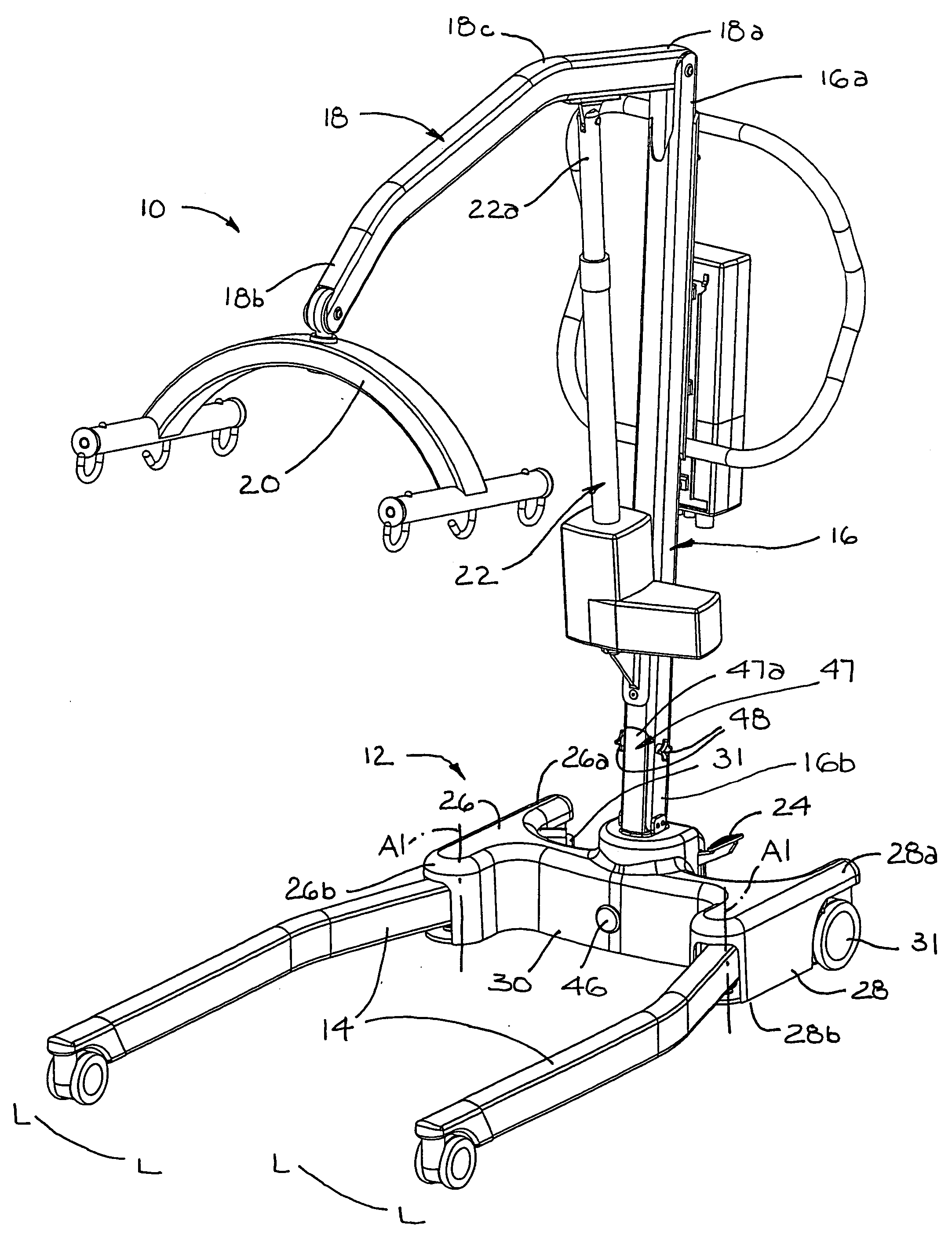
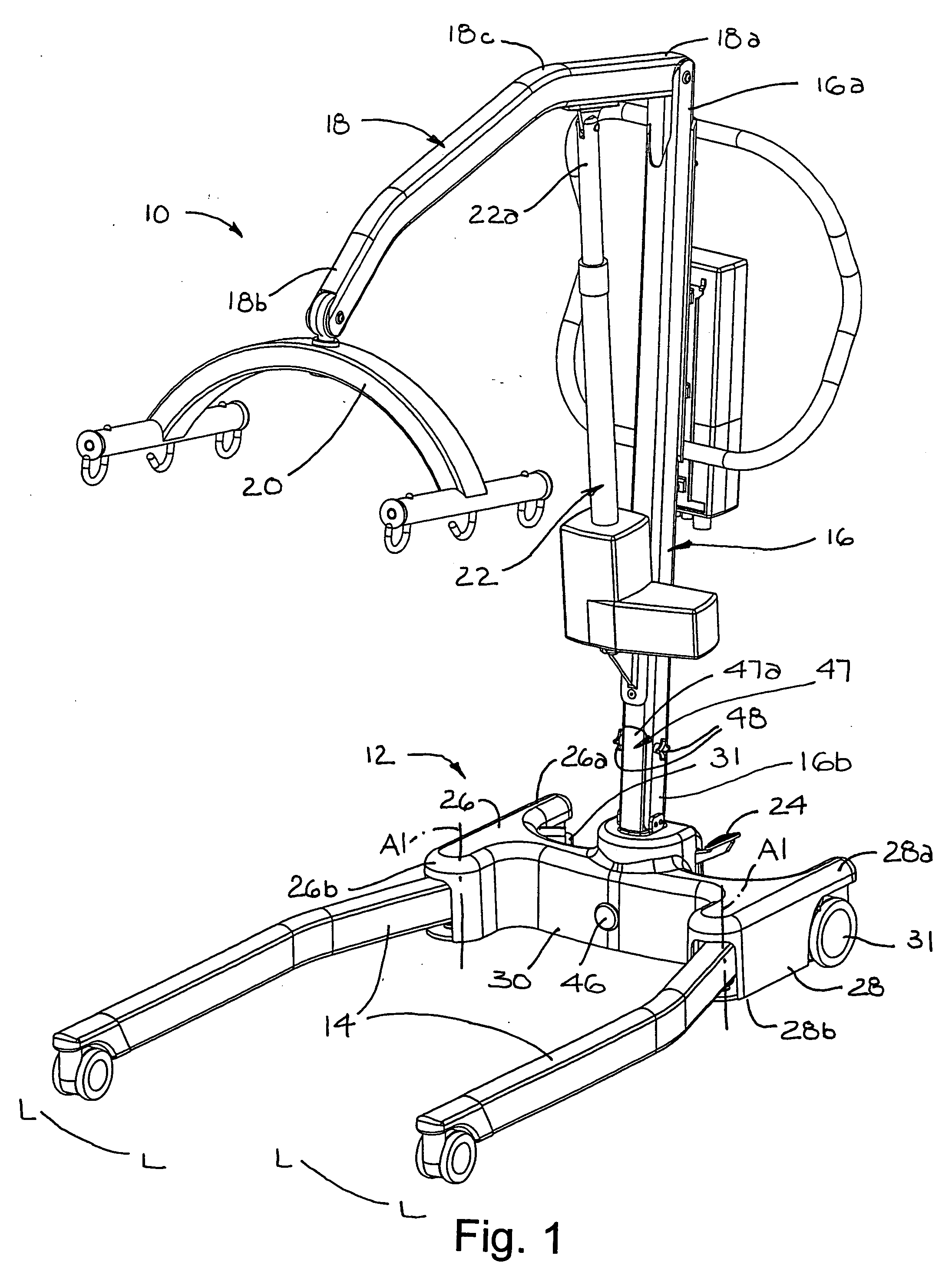
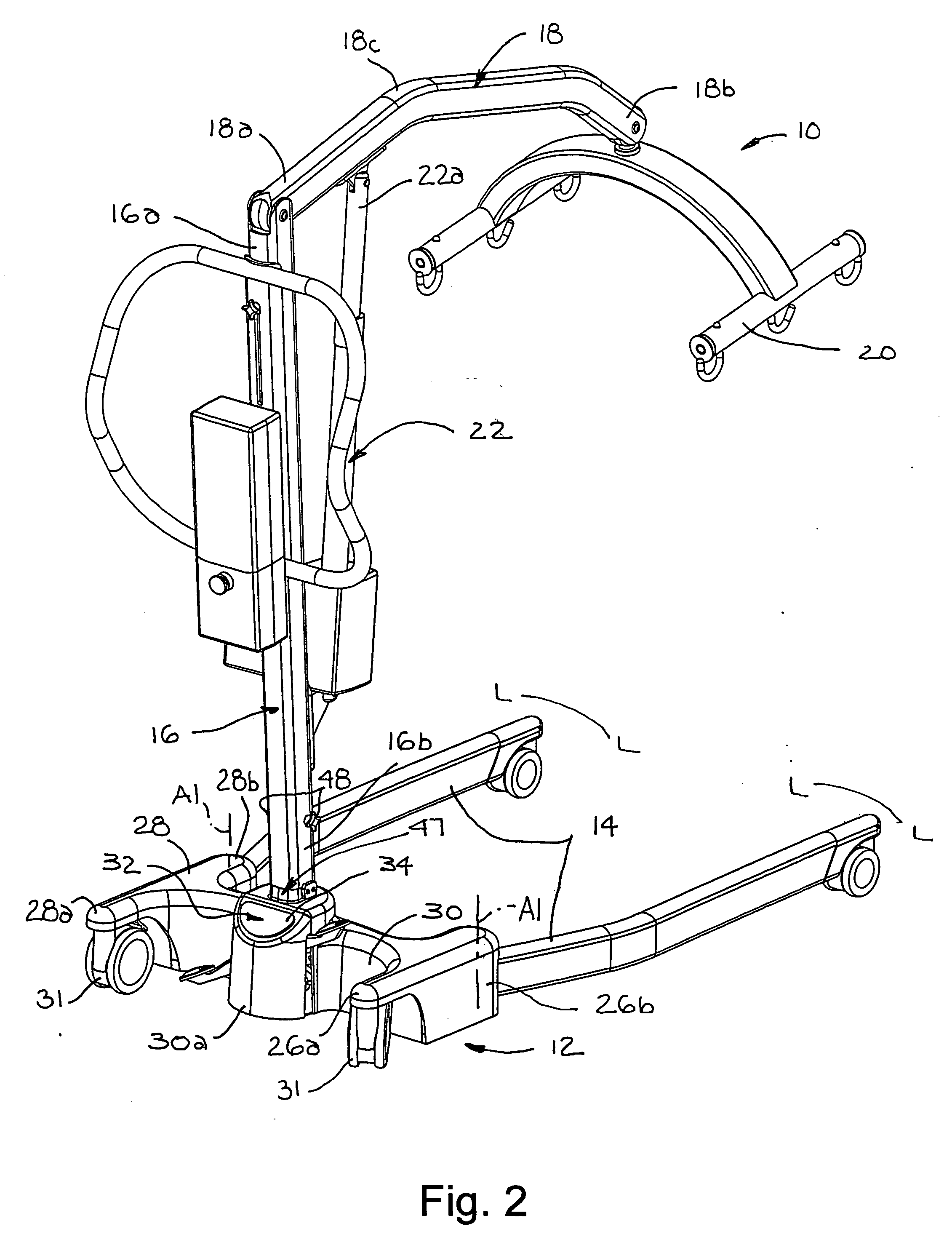
[0013] Referring now to the drawings, there is illustrated in FIGS. 1 and 2 a portable lift, generally indicated at 10. The lift preferably includes a base 12, a pair of displaceable support legs 14 extending horizontally from the base 12, a mast 16 extending vertically from the base 12, and a boom 18 extending from an upper end 16a of the mast 16. The mast 16 is preferably not telescopic, but rather a single piece. The boom 18 is pivotally connected at one end 18a to the mast 16, and the boom 18 has a cradle 20 at its other end 18b for lifting patients (not shown). An actuator 22 is mounted part way up the height of the mast 16, and is connected at its far end 22a to an intermediate portion 18c of the boom 18 so that actuation of the actuator 22 pivots the boom 18 relative to the mast 16. During operation, the legs 14 can be opened and closed to (e.g., along the lines L-L) accommodate the operating needs of the lift 10. The opening and closing motion is accomplished by operation of...


PUM


Abstract

A patient lift comprises a base and a foot push pad integrated with the base. The foot push pad provides a high-friction surface to reduce risk that an operator's foot will slip off the base.

Description

BACKGROUND OF INVENTION [0001] This invention relates in general to hoisting equipment and more particularly, to a portable lifting apparatus for lifting and moving incapacitated persons. [0002] Lifting devices are well known. Such devices typically include a base, a mast extending upwardly from the base, and a boom extending forwardly from the mast. The boom generally supports a cradle by which the patient can be completely suspended from the lifting device. Rollers depending from the base enable the device and thus the patient to be moved. [0003] Ease in moving a patient is critical to the function of the lifting device. It is well known to provide lift devices with handles that may be grasped by an operator to move or manipulate the lifting device when moving a patient. In addition, the operator of a conventional lift may put his or her foot on the lift base when moving or manipulating the lift. Force from the foot gives the operator extra leverage and / or control over the lift. H...

Claims


Application Information

Patent Timeline
Patent Type & Authority Applications(United States)
IPC IPC(8): A61G7/14
CPCA61G7/1017A61G7/1074A61G7/1067A61G7/1046
Inventor BAIN, COLIN C.HEALES, NIGELGENSKE, DAVID
Owner SUNRISE MEDICAL HHC INC
Why Eureka
Try Eureka