Subsurface drainage system

a drainage system and subsurface technology, applied in the field of subsurface drainage system, can solve the problems of time and labor for watering, difficult to uniformly heat or cool the root zone layer without employing a dense network of pipes, and difficulty in maintaining healthy grasses

Inactive Publication Date: 2006-02-09
AIRFIELD SYST
View PDF3 Cites 24 Cited by
  • Summary
  • Abstract
  • Description
  • Claims
  • Application Information

AI Technical Summary

Problems solved by technology

Such watering requires time and labor.
Additionally, temperature variation can cause problems in maintaining healthy grass for certain temperature sensitive grasses.
The problem encountered with such pipin

Method used


Image

  • Subsurface drainage system
  • Subsurface drainage system
  • Subsurface drainage system

Examples


Embodiment Construction

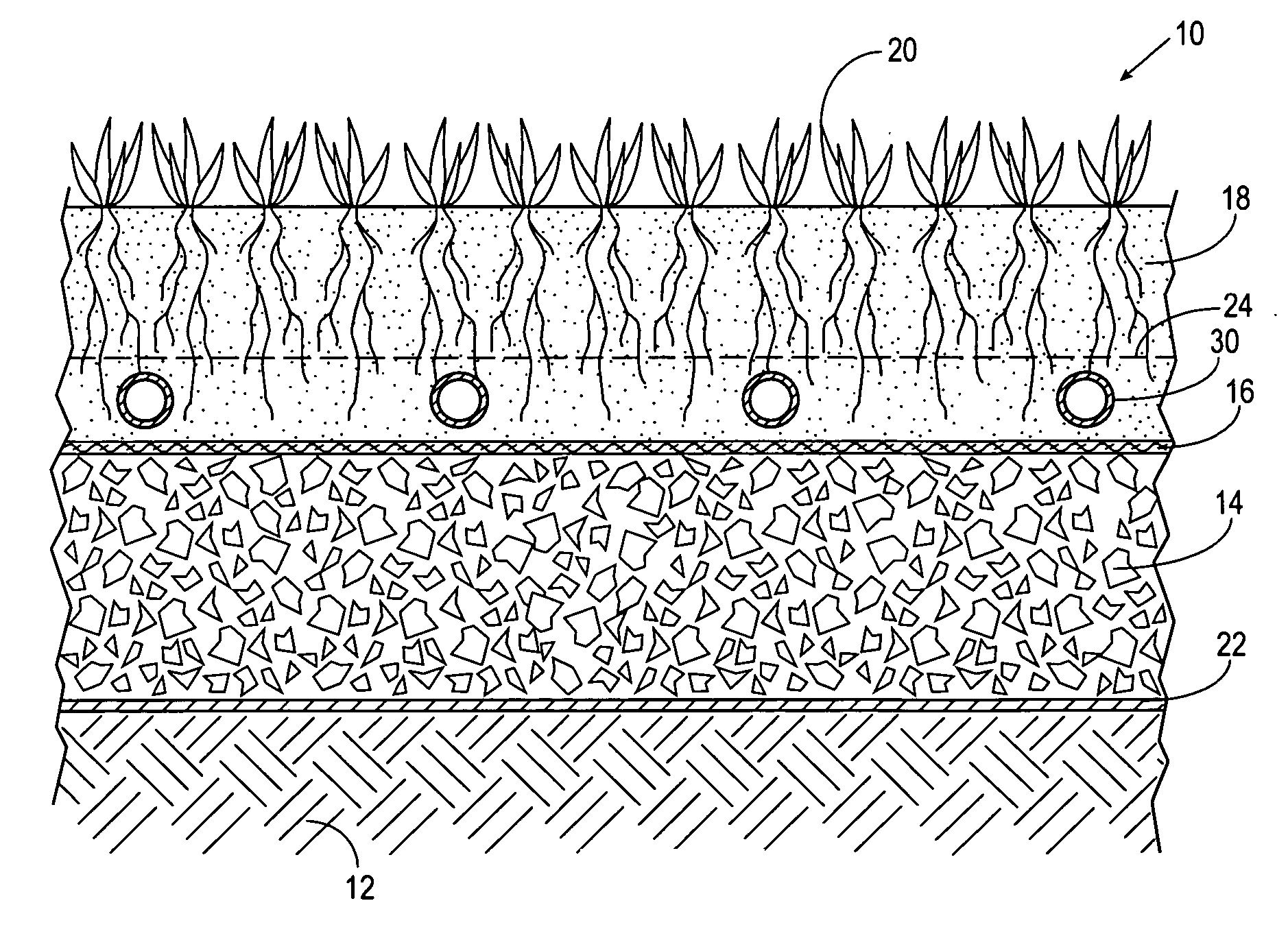
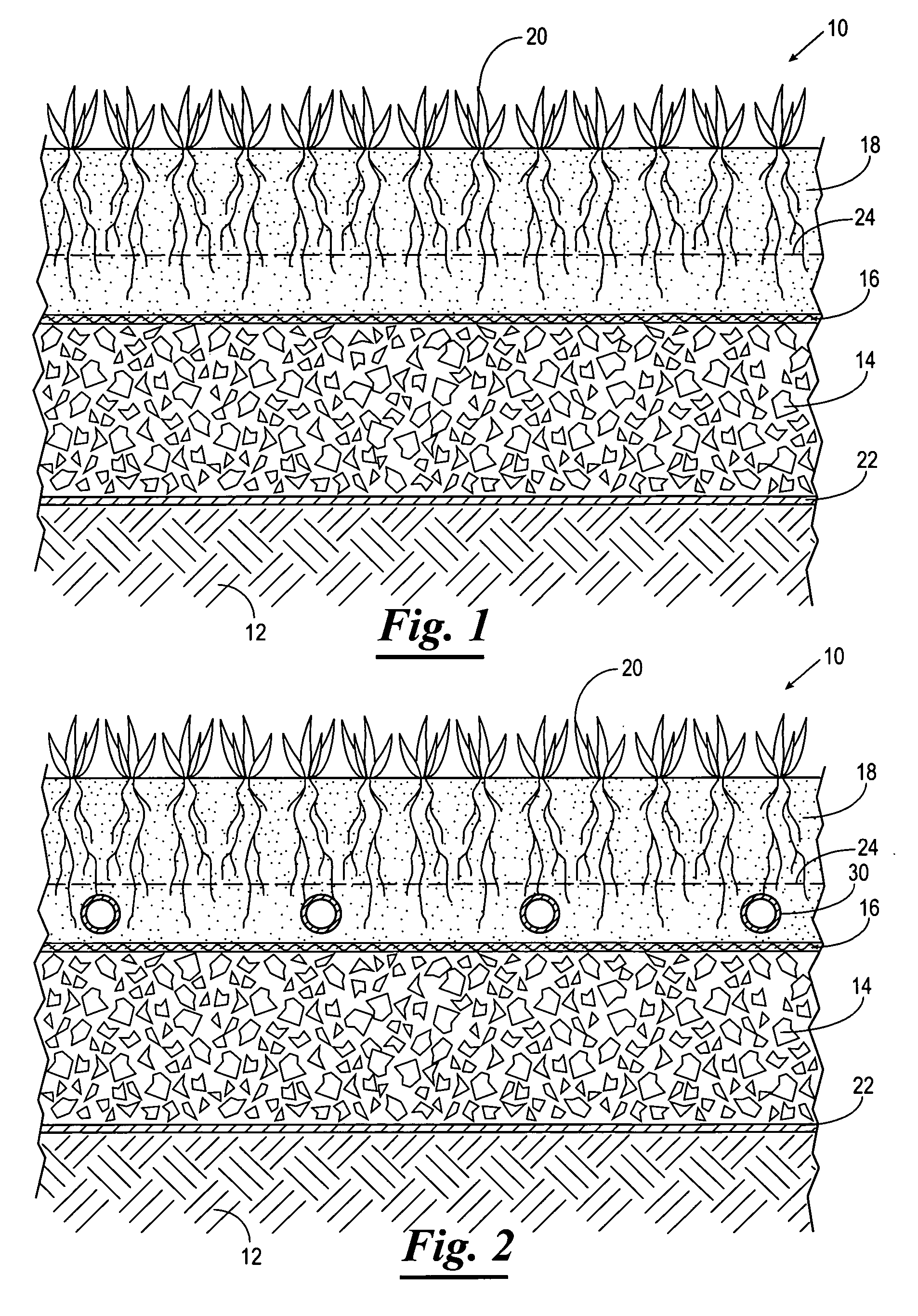
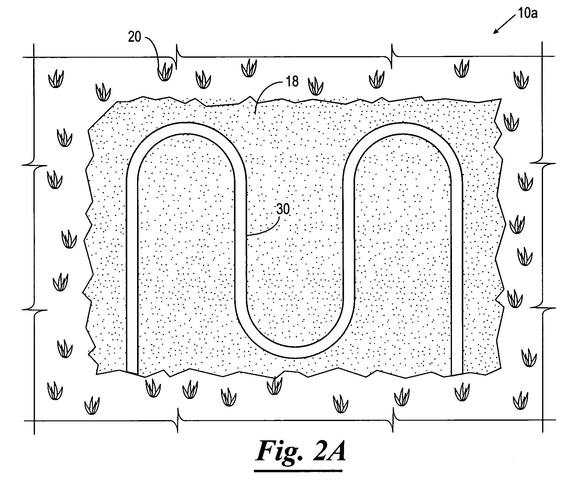
[0015] Referring now to the drawings, and more particularly to FIG. 1, shown therein is a subsurface drainage system 10 constructed in accordance with the present invention. The subsurface drainage system 10 is similar to that recommended by the United States Golf Association for the construction of putting greens with the exception that the subsurface drainage system 10 includes a semi-permeable filter fabric layer at the bottom of the root zone layer. The 2004 revisions of the USGA Recommendations for a Method of Putting Green Construction is hereby expressly incorporated herein by reference. More particularly, the subsurface drainage system 10 of the present invention includes a subgrade or base 12, an intermediate layer 14, a semi-permeable filter fabric layer 16, an upper or root zone layer 18, and a turf layer 20. Optionally, an impermeable liner 22 is disposed between the base layer 12 and the intermediate layer 14. In instances where it is desirable to allow some permanent d...


PUM


Abstract

The present invention is directed to a subsurface drainage system for a playing surface. The subsurface drainage system includes a subgrade, an intermediate layer disposed over the subgrade, a layer of semi-permeable filter fabric disposed over the intermediate layer, an upper permeable layer disposed over the layer of filter fabric and on which the playing surface is disposed, and a hydronic piping network disposed in the upper layer near the layer of filter fabric. The layer of filter fabric has a permeability less than the permeability of the intermediate layer and such that the layer of filter fabric functions as a perching layer to support a perched water table above the filter fabric. The hydronic piping network is positioned within the perched water table such that the water of the perched water table functions as a heat exchanger to facilitate heating and cooling of the upper layer upon the hydronic piping network being heated or cooled.

Description

CROSS REFERENCE TO RELATED APPLICATIONS [0001] This application claims benefit of U.S. Provisional Application No. 60 / 600,095, filed Aug. 9, 2004, which is incorporated herein by reference in its entirety.BACKGROUND OF THE INVENTION [0002] 1. Field of the Invention [0003] The present invention relates to a subsurface drainage system for facilitating water drainage from a land surface, and more particularly but not by way of limitation, to improved subsurface drainage system for an athletic field, such as a putting green or football field, which subsurface drainage system is capable of retaining adequate water to facilitate turf growth and temperature regulation while promoting rapid infiltration of water through the subsoil structure. [0004] 2. Brief Description of Related Art [0005] Conventionally, drainage for athletic fields, such as football fields and putting greens, has been constructed with the use of a network of drain pipe buried under the playing surface. The drain pipe is...

Claims


Application Information

Patent Timeline
IPC IPC(8): E02B11/00
CPCE01C13/08E02B11/00E01C13/083
Inventor BLACKWOOD, CHARLES R.COURTER, JAMES M.BLACKWOOD, CHARLES F.
Owner AIRFIELD SYST
Why Eureka
Try Eureka