Valve for mixing cold and hot water

a technology for mixing valves and hot water, applied in the field of valves, can solve the problems of difficult and fast rotation or change of plates, and achieve the effect of easy and quick rotation or chang

Inactive Publication Date: 2006-02-16
YANG TSAI CHEN
View PDF7 Cites 10 Cited by
  • Summary
  • Abstract
  • Description
  • Claims
  • Application Information

AI Technical Summary

Benefits of technology

[0010] The other objective of the present invention is to provide a valve which includes a plate that may be easily and quickly rotated or changed relative to the valve receptacle and the valve cover without opening or disassembling the valve receptacle and the valve cover and the valve receptacle.

Problems solved by technology

However, after the valve is engaged into and received in a valve receptacle, and when it is required to rotate or change the plate relative to the valve receptacle and the valve cover, it is required to open or disassemble the valve receptacle and the valve cover and the valve receptacle, before the plate may be rotated or changed relative to the valve receptacle and the valve cover for about 180 degrees; i.e., the plate may not be easily and quickly rotated or changed relative to the valve receptacle and the valve cover without opening or disassembling the valve receptacle and the valve cover and the valve receptacle.

Method used


Image

  • Valve for mixing cold and hot water
  • Valve for mixing cold and hot water
  • Valve for mixing cold and hot water

Examples


Embodiment Construction

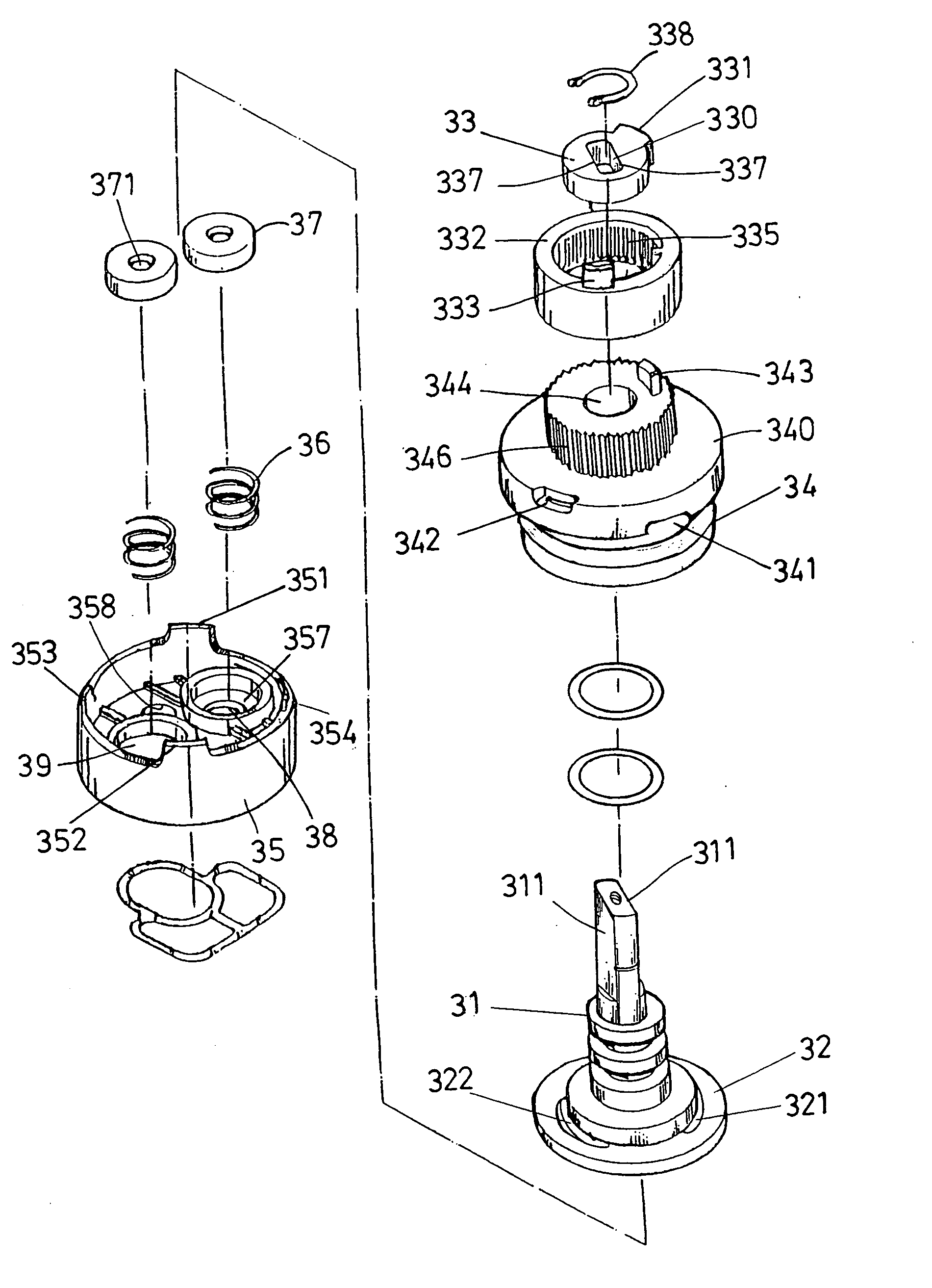
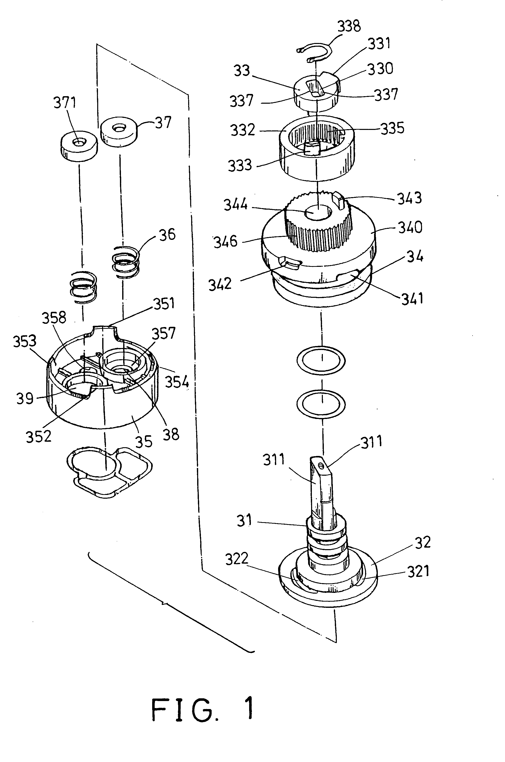
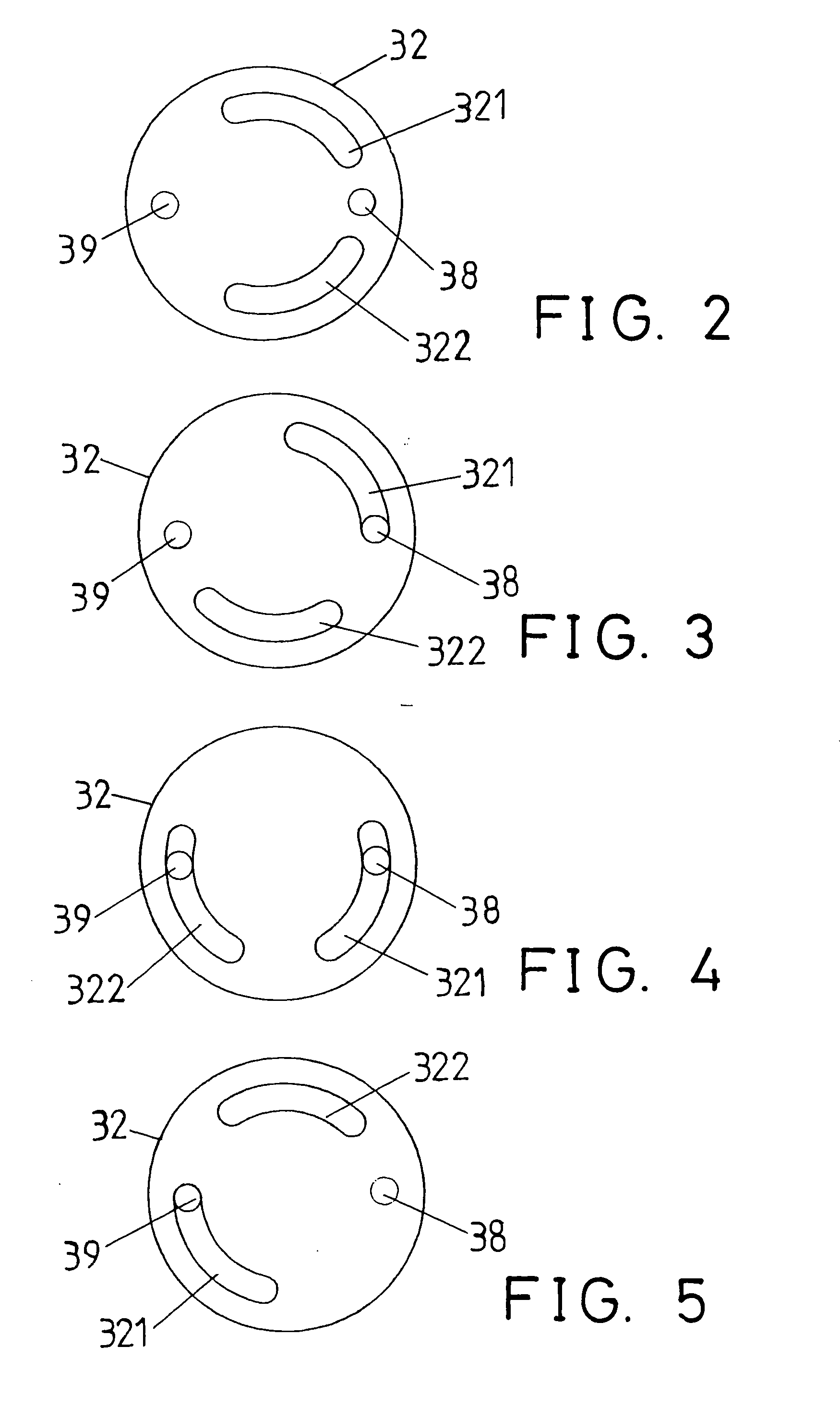
[0019] Referring to the drawings, and initially to FIGS. 1-3, a valve in accordance with the present invention comprises a housing 34 including a peripheral flange 340 extended radially outward from the middle portion thereof, and including one or more pairs of notches 341 oppositely formed in the bottom portion of the peripheral flange 340 of the housing 34, and including one or more pairs of channels 342 oppositely formed therein.

[0020] Two notches 341 and two channels 342 are shown in the drawings and are oppositely formed in the housing 34; i.e., the notches 341 are arranged 180 degrees apart from each other, and the channels 342 are also arranged 180 degrees apart from each other. The position between the notches 341 and two channels 342 are not required lo be predetermined, but may not be aligned with each other.

[0021] It is preferable that the notches 341 and the channels 342 are arranged 90 degrees, but not necessarily be limited to this degree, apart from each other. The ...


PUM


Abstract

A valve includes a housing having a projection, a plate having a stem rotatably received in the housing, a follower having an oblong orifice for receiving the stem, and defined by two parallel and symmetric engaging flat surfaces for engaging with the engaging flat surfaces of the stem and for allowing the follower to be anchored to and rotated in concert with the stem. The follower includes an extension for engaging with the projection. An engagement of the parallel and symmetric engaging flat surfaces of the stem and of the follower allows the follower to be engaged onto the stem after the stem has been rotated relative to the base, without rotating the follower relative to the base.

Description

BACKGROUND OF THE INVENTION [0001] 1. Field of the Invention [0002] The present invention relates to a valve, and more particularly to a valve for mixing cold and hot water. [0003] 2. Description of the Prior Art [0004] Typical valves for mixing cold and hot water comprise a first inlet coupled to a cold water reservoir and a second inlet coupled to a hot water reservoir for receiving the cold water and the hot water from the cold water reservoir and the hot water reservoir respectively. The typical valves further include a control mechanism for controlling the flowing and / or the mixing of the cold water and the hot water. [0005] When the first inlet is wrongly coupled to the hot water reservoir and when the second inlet is wrongly coupled to the cold water reservoir, the cold water and the hot water may be wrongly supplied into the valve such that the valve, particularly the knob of the valve may be operated in different actuation or rotation directions from that of the usual direc...

Claims


Application Information

Patent Timeline
Patent Type & Authority Applications(United States)
IPC IPC(8): F16K11/074
CPCF16K11/0743Y10T137/86823
Inventor YANG, TSAI CHEN
Owner YANG TSAI CHEN
Why Eureka
Try Eureka