Pipe beveling system

a beveling system and pipe technology, applied in the field of beveling systems, can solve the problems of difficult manual holding of the saw, o-ring damage, and excessive resistance, and achieve the effects of convenient operation, quick and easy change, and simple operator adjustmen

Inactive Publication Date: 2006-08-01
DUNCAN C WARREN +2
View PDF14 Cites 25 Cited by
  • Summary
  • Abstract
  • Description
  • Claims
  • Application Information

AI Technical Summary

Benefits of technology

[0015]The present invention utilizes a beveling cutting bit based upon the type of router bit commonly used in the woodworking industry, but with extensive modifications and a unique holding chuck. The beveling tool of the invention can be easily attached to and detached from a wide variety of power tools safely and conveniently. Moreover, the bevel depth can be quickly and easily changed from among several standard, reproducible bevel depth cuts with a simple operator adjustment performed using only a screwdriver.
[0016]One primary object of the invention is to provide a pipe beveling tool that can be used to bevel the cut ends of pipes on a job site that can be used quickly and easily by attachment to a variety of different power tools. Moreover, the beveling tool of the invention can be attached to and detached from power tools, such as a power saw, without disturbing the attachment of the sawblade to the saw.
[0017]Another primary object of the invention is to provide a pipe beveling tool that can be quickly and easily adjusted to several different commonly specified pipe bevels. The adjustment of the tool to each bevel depth is highly reliable and easily reproducible. Adjustment maybe performed quickly and easily using only a screwdriver.
[0018]A further object of the invention is to provide a pipe beveling tool that is highly stable and which are resists bending moment forces applied perpendicular to the axis of rotation. This results in a uniform, even bevel around the circumference of the pipe end. Furthermore, due to its construction the tool of the invention is unlikely to break off at its coupling connection to the power tool to which is attached.

Problems solved by technology

As a consequence, any excess resistance that might be present as a result of an O-ring being damaged cannot be felt when large pipe sections are forced together.
This can be dangerous if the blade is not designed to be used as a grinder.
There have been instances of composite, cut off wheels exploding due to the erosion of the reinforcement and abrasive on the sides of the blades.
Furthermore, it is very difficult to manually hold the saw so as to produce a uniform bevel of a specific chamfer angle throughout the entire perimeter of the cut end of the pipe.
As a consequence, the bevel can be too shallow or two deep.
If a bevel is cut too shallow, the gap for the O-ring is too small and the O-ring cannot fit into it to create a seat during the coupling of two pipe sections.
In either case, the O-ring is improperly seated and leaking can occur at the pipe coupling.
If too much bevel is attempted then a fine and easily damaged edge is produced on the pipe which creates additional problems.
In addition, if an edge is created, any powered hand beveler will lose one of the guiding surfaces and an irregular cut will be produced.
One significant disadvantage of this tool is that the adjustments are not easily reproducible.
That is, there is no reliable way for the operator to return the beveling cutter head to a previously selected position of extension from the outboard end of the tubular body.
Consequently, beveling depths are not readily reproducible using this tool since there is no easy, reliable way of changing the depth of the bevel cut and then returning to a prior bevel cut setting.
Furthermore, loosening and tightening of the positioning nuts is rather difficult.
Access to one of the positioning nuts is through a slot in the body which is not easily accessible.
Moreover, wrenches of two different sizes must be employed in separate operations to untighten both positioning nuts and then retighten them.
A further disadvantage of this tool is that head is mounted to the arbor of a power saw by a threaded inboard shank that has the same pitch and diameter of a conventional arbor saw bolt.
Because of the relatively large balk of the tool, as contrasted to an arbor bolt head, there is a considerable longitudinal bending moment applied to the inboard shank of the tool during the beveling operation.
Consequently, the mounting shank of the tool is quite likely to break, and frequently does so.
A further disadvantage of this tool is that it cannot be attached to and detached from a power saw without uncoupling the attachment of the saw to the saw blade arbor.
Consequently, the tool cannot be quickly and easily removed from or attached to a conventional power saw.
Moreover, the coupling arrangement employed limits use of the tool to attachment to only a particular type of power saw having a particular type of saw blade mounting.

Method used


Image

  • Pipe beveling system
  • Pipe beveling system
  • Pipe beveling system

Examples


Embodiment Construction

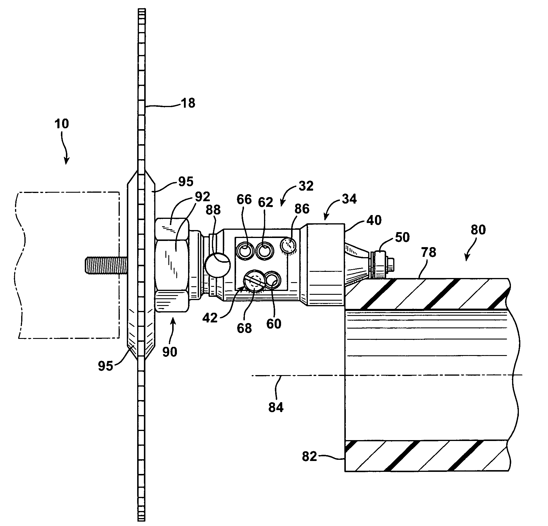
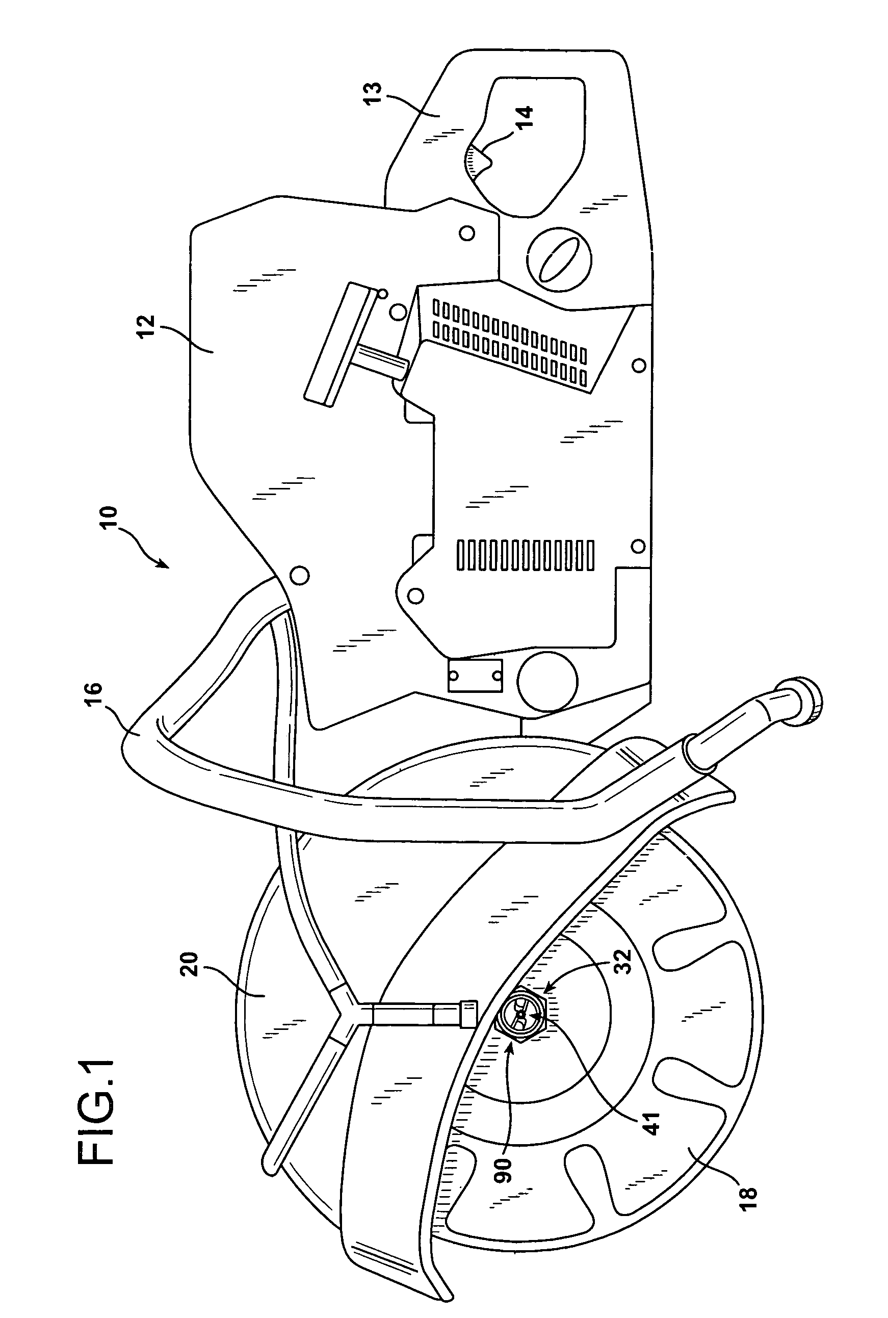
[0040]FIG. 1 illustrates a pipe cutting saw indicated generally at 10 having a small gasoline powered engine in the body area 12, a rear handgrip 13 housing a trigger 14, a front stabilizing handgrip 16, and a pipe cutting blade 18 partially surrounded by a protective blade guard 20. In addition, a pipe beveling tool 32 according to the invention is attached to the pipe cutter 10 for coaxial rotation with the sawblade 18 by means of an elongated arbor bolt 33, which is visible in FIG. 4.

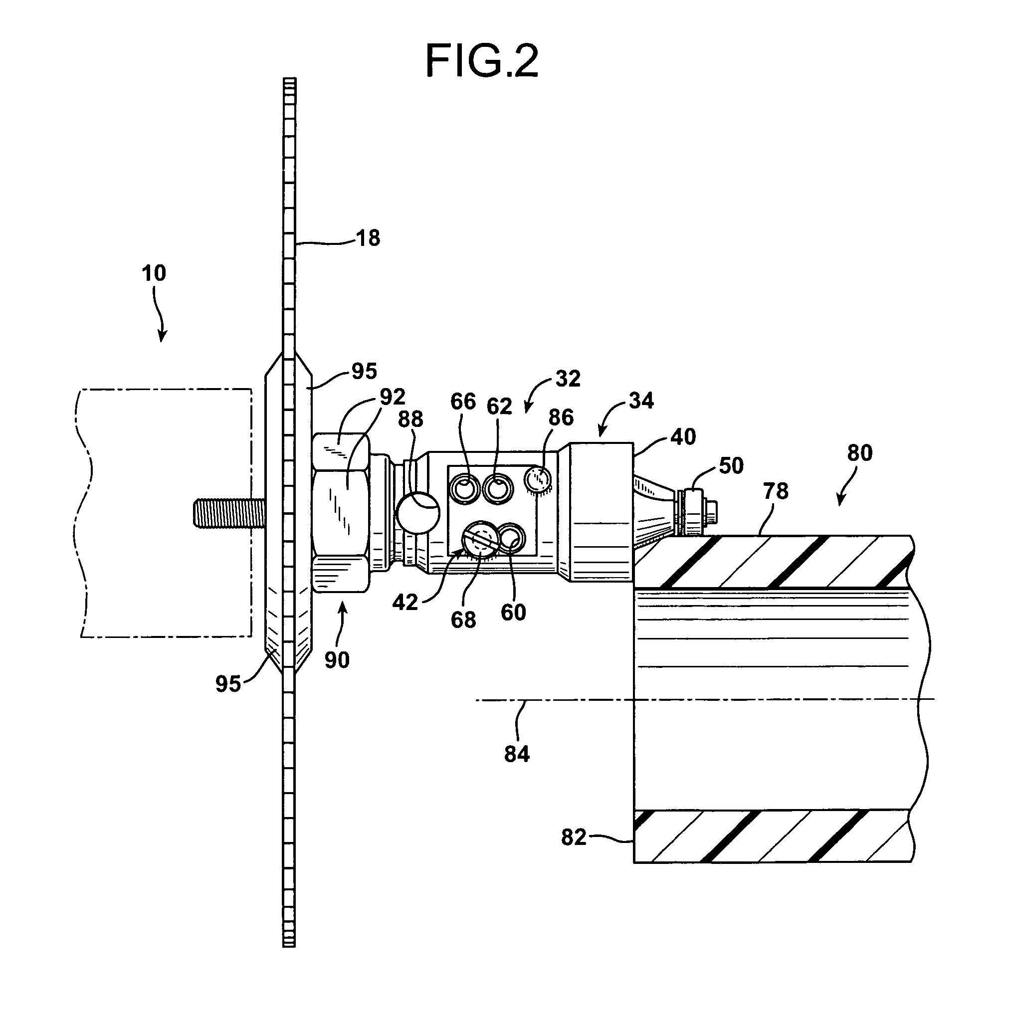
[0041]The pipe beveling tool 32 and its connection to the pipe cutting saw 10 is illustrated in greater detail in FIGS. 2 and 4. As illustrated in the drawing figures, the beveling tool 32 is comprised of a hollow, barrel-shaped tubular body 34 having a central, longitudinal axis of rotation 36, an inboard end 38, and an opposite, outboard cylindrical annular end 40. The pipe beveling tool 32 is also comprised of a core member 41 and a latching pin in the form of an adjusting screw 42.

[0042]The core ...


PUM

PropertyMeasurementUnit
longitudinal distancesaaaaaaaaaa
rotationaaaaaaaaaa
diameteraaaaaaaaaa

Abstract

A tool for beveling the end of a pipe is comprised of a hollow, tubular body having a central, longitudinal axis of rotation, an inboard coupling end, and an opposite outboard working end. A plurality of longitudinally spaced, transversely directed latching pin bores of equal size are defined through the wall of the tubular body. A core member is disposed coaxially within the tubular body. The core member includes a beveling cutter head and a longitudinal stem having a radially inwardly directed, circumferential latch position groove. A transversely oriented latching pin is engaged in a selected one of the latching pin bores in the body and with the latch position groove of the core stem. This allows alternative selection of each of the latch position bores for insertion of the latching pin. The particular bore selected determines the longitudinal position of the core stem latch position groove within the body that will be aligned with the latching pin. This, in turn, determines the extent of protrusion of the core member cutter head from the outboard end of the tubular body, and thus the depth of the beveling cut in the pipe.

Description

BACKGROUND OF THE INVENTION[0001]1. Field of the Invention[0002]The present invention relates to a tool for beveling an end of a pipe cut on site during a pipe laying installation.[0003]2. Description of the Prior Art[0004]Sections of pipe that are to be utilized in subsurface applications such as drainpipes, cable pipes, gas line pipes, and oil pipelines are cut to specific lengths when they are manufactured. During the pipe section fabrication process, particularly with large diameter pipes, the sections of pipe are often created with an enlarged bell or socket connection at one end, and are beveled or chamfered at the other end. Sections of pipe must be beveled so as to accommodate an O-ring gasket to ensure a fluid-tight connection between the adjacent pipe sections. An enlarged socket or bell coupling is required to prevent the O-ring from being damaged during the laying of the pipe. When a pipe line is laid the beveled end of each section of pipe is inserted into the larger so...

Claims


Application Information

Patent Timeline
Patent Type & Authority Patents(United States)
IPC IPC(8): B23P23/00B23B5/16B23C3/12
CPCB23B5/168B23C3/122B27B5/29Y10T279/17821Y10T409/304144Y10T82/22Y10T409/308624Y10T279/3487Y10T29/5199Y10T29/5148Y10T83/0596
Inventor DUNCAN, C. WARRENGLYNN, BILLROOT, BRUCE
Owner DUNCAN C WARREN
Why Eureka
Try Eureka