
Spontaneous full fuel tank indicator

Inactive Publication Date: 2006-02-16
ROSSI MARC A
View PDF5 Cites 33 Cited by
  • Summary
  • Abstract
  • Description
  • Claims
  • Application Information

AI Technical Summary

Benefits of technology

[0009] The invention provides a means by which an operator positioned at the fuel fill aperture of a motor vehicle is informed that the fuel tank has been completely filled. The driving distance that can be realized is maximized by indicating to the operator whether the tank has actually been filled to capacity when the automatic shut off by the pump nozzle initially stops the flow of fuel into the tank. If the tank has not been completely filled, the operator can safely add additional fuel to the tank so as to achieve more driving time before another refueling stop is required.
[0010] This invention further provides an immediate indication of the fill status of the fuel tank so as to preclude the operator from having to return to the driver's seat and turn the key in the ignition switch in order to observe the fuel gauge. Returning to the driver's seat is time-consuming and potentially hazardous if the fuel pump nozzle remains engaged in the fill pipe. Avoiding the risk by returning the nozzle to the pump terminates the refueling process and requires that the process be repeated if more fuel is to be added. The present invention eliminates the need for risk exposure or additional time spent at the filling station in order to obtain a legitimate full tank.
[0011] This invention further provides a means by which an operator who is cognizant of the fact that the tank of his vehicle is not full when the pump is automatically shut off, or an operator at a pump without an automatic shut-off, can safely continue the refueling process. This invention indicates to the operator at the fuel fill aperture the point at which full capacity has been reached so that the operator is able to discontinue pumping prior to overfilling the tank.

Problems solved by technology

Returning to the driver's seat is time-consuming and potentially hazardous if the fuel pump nozzle remains engaged in the fill pipe.

Method used


Image

  • Spontaneous full fuel tank indicator
  • Spontaneous full fuel tank indicator
  • Spontaneous full fuel tank indicator

Examples


Embodiment Construction

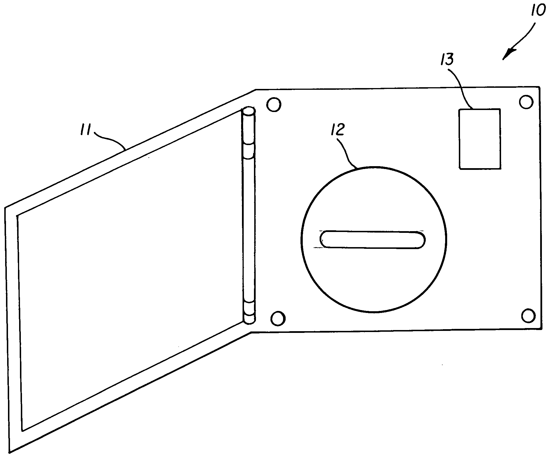
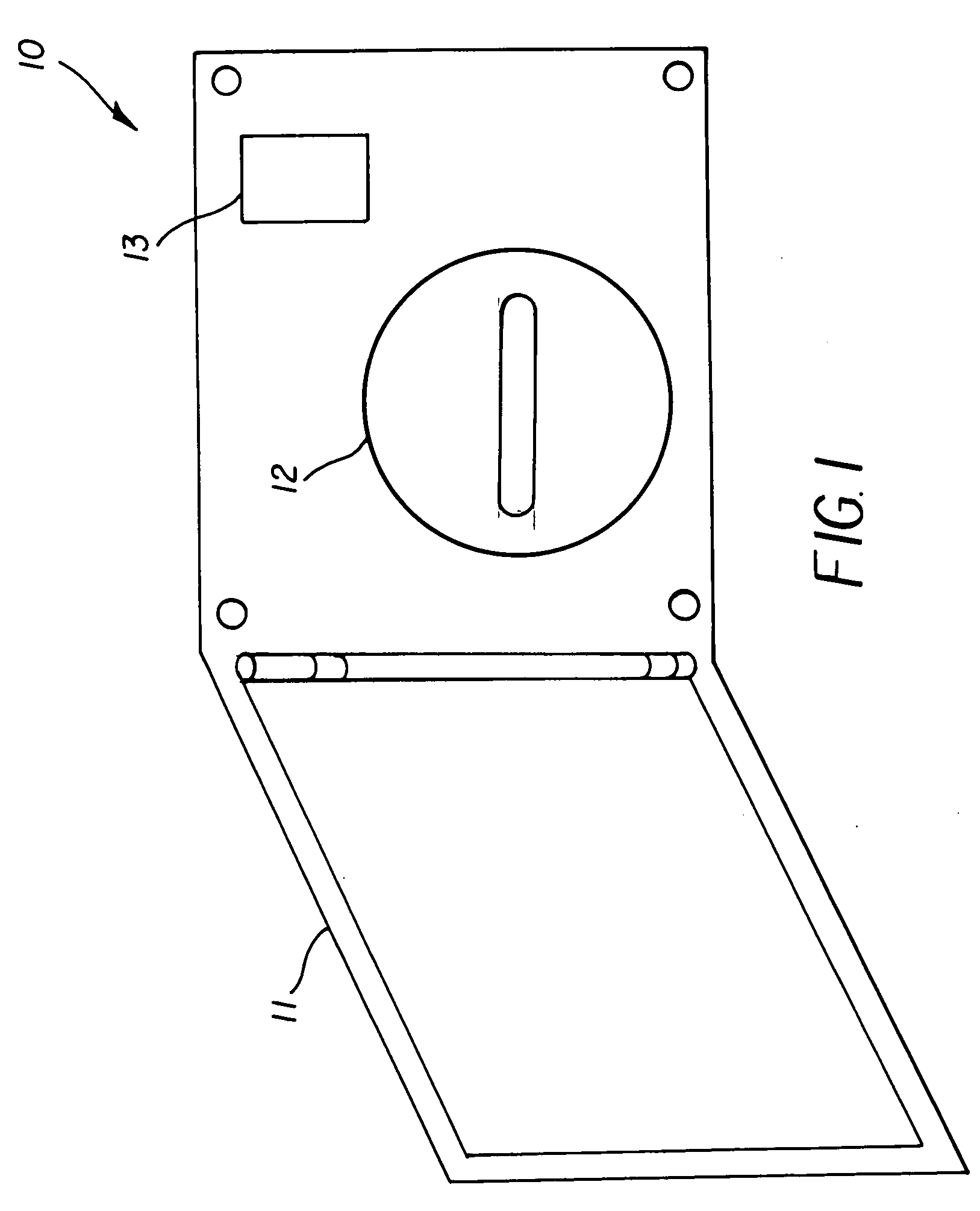
[0017] Referring to FIG. 1, there is a fuel tank filler assembly 10 equipped with the present invention. A fuel cap cover door II is in an open position revealing the presence of a fuel cap 12 and an indicator 13, located in near proximity to the fuel cap 12 and protected by the fuel cap cover door 11 when the fuel cap cover door 11 is in a closed position.

[0018] Operation of the spontaneous full fuel tank indicator occurs in the following manner. As the vehicle fuel tank is filled., a liquid level sensor positioned in the fuel tank detects the fluid level in the fuel reservoir. A liquid level sensor is commonly present in vehicles to operate the fuel tank gauge located on the dashboard. A variety of liquid level sensors exist, including float switches, space electrodes and capacitance type sensors. When the liquid level sensor detects a fluid level at a maximum position, the indicator 13, coupled with the liquid level sensor, contemporaneously conveys the filled status to the vehi...


PUM

PropertyMeasurementUnit
Timeaaaaaaaaaa
Levelaaaaaaaaaa

Abstract

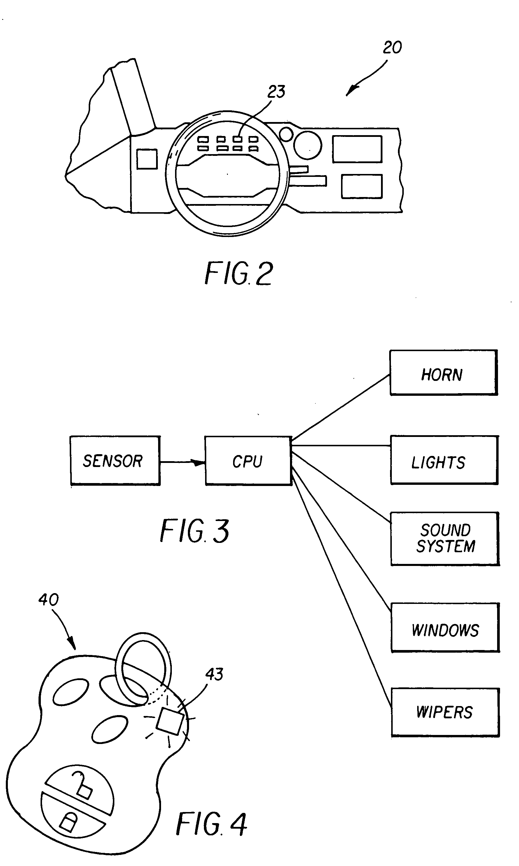
A spontaneous full fuel tank indicator is disclosed that allows an operator stationed at the fuel fill aperture of a motor vehicle to know when the fuel tank is completely filled. The indicator may be a visual display or an audible alert. The indicator may also be the CPU operation of a vehicle member such as the honking of the horn, flashing of the lights, or operation of the vehicle sound system. Alternatively, the indicator may be a visual, audible or vibratory alert at a key fob. The full fuel tank indicator operates in real-time without requiring a key in the ignition switch. A converter kit is also disclosed by which an existing vehicle may be equipped with a spontaneous full fuel tank indicator.

Description

BACKGROUND OF INVENTION [0001] This invention relates in general to an apparatus for a motor vehicle for the detection of a full fuel tank. In particular, the apparatus provides a real time confirmation detectable at the fuel fill aperture that the fuel tank has been filled to capacity. [0002] Gasoline powered motor vehicles require the periodic addition of fuel to the fuel tank. When adding gasoline to the vehicle, it is common practice to attempt to fill the fuel tank to its capacity so as to maximize the driving distance that can be achieved before the fuel tank is depleted again. In most instances, an operator adds fuel by one of two methods: (1) standing at the vehicle fuel fill aperture to the fill pipe while manually depressing the trigger of a fuel pump nozzle that has been inserted into the fill pipe so as to allow fuel to flow into the gas tank, or (2) initially inserting the fuel pump nozzle into the fuel fill area, depressing the nozzle trigger, and then using a trigger ...

Claims


Application Information

Patent Timeline
IPC IPC(8): B65B31/00
CPCG01F23/0069B60K15/04G01F23/802
Inventor ROSSI, MARC A.
Owner ROSSI MARC A
Learn More