Vehicle hybrid energy system

A technology of hybrid energy and energy storage system, applied in the field of hybrid energy storage system, to achieve the effect of improving driving characteristics and prolonging life

Inactive Publication Date: 2010-06-16
RGT UNIV OF MICHIGAN
View PDF0 Cites 4 Cited by
  • Summary
  • Abstract
  • Description
  • Claims
  • Application Information

AI Technical Summary

Problems solved by technology

The resulting disadvantages are not optimal energy transfer, volumetric dimensions, weight and complexity of work (number and configuration of units, monitoring of normal and fault status of units, etc.)

Method used


Image

  • Vehicle hybrid energy system
  • Vehicle hybrid energy system
  • Vehicle hybrid energy system

Examples


Embodiment Construction

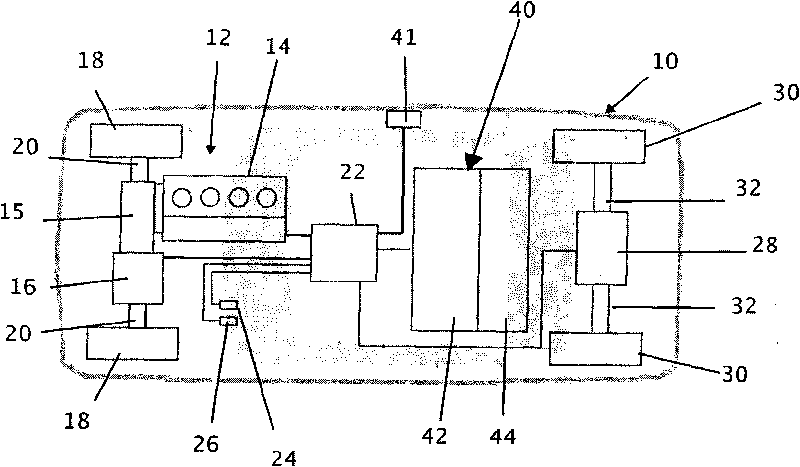
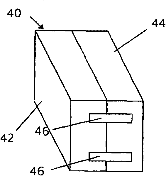
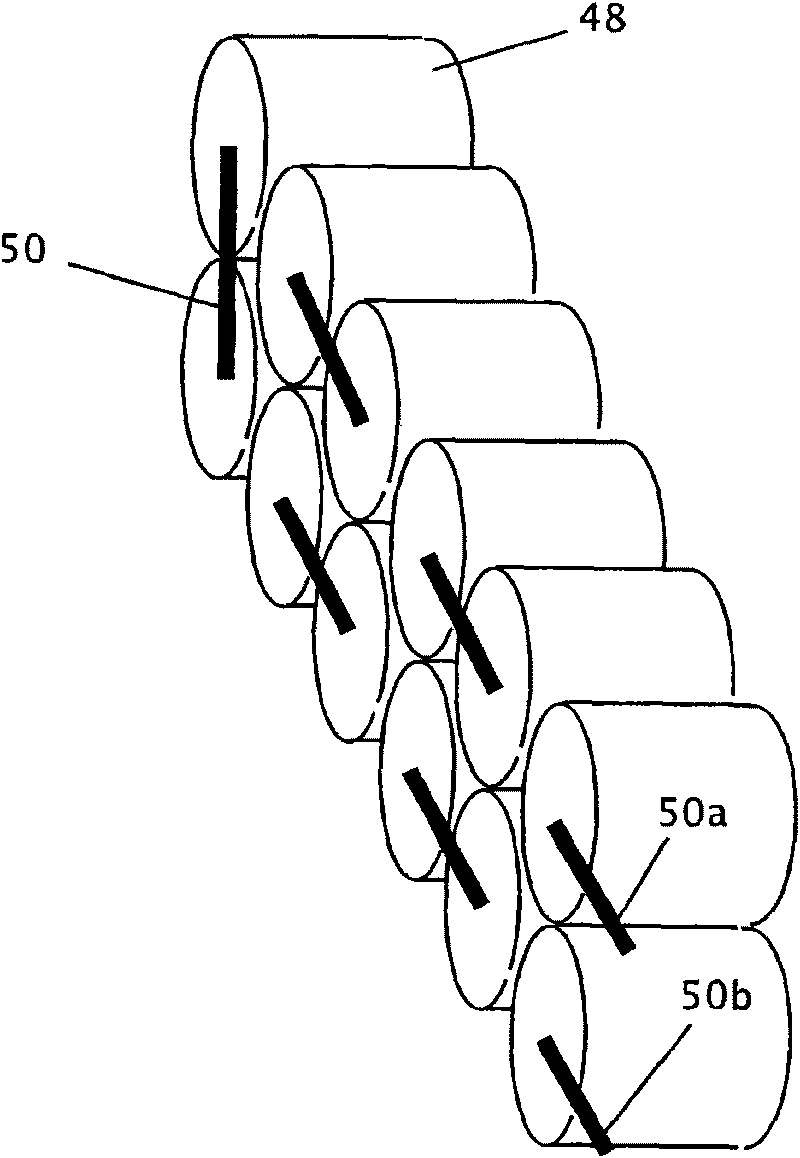
[0016] By abandoning single-architecture storage systems for a hybrid approach, energy storage system performance can be significantly improved for electric vehicle (EV), hybrid electric vehicle (HEV) and plug-in hybrid electric vehicle (PHEV) applications. A hybrid energy storage system can be generally understood as a system comprising two or more different energy storage structures. For example, a hybrid energy storage system may contain two different battery chemistries and corresponding cell configurations. By optimizing a hybrid energy storage system, the overall size, weight, number of cells, and control complexity can be reduced, and energy transfer and system lifetime can be improved. An energy storage system has multiple modules. A module may include a group of units having specific characteristics such as unit configuration, unit chemistry, controls, and the like. Combining different types of modules may allow improved energy transfer over a wider range of operati...


PUM


Abstract

A hybrid energy storage system suitable for use in a vehicle having an electrified drivetrain includes a first energy storage module and a second energy storage module that is different than the first energy storage module. The first energy storage module may have a cell configuration, a cell chemistry, a cell number, a controller or another characteristic different than a like characteristic of the second energy storage module.

Description

technical field [0001] The present invention relates to energy storage systems. More particularly, the present invention relates to energy storage systems for electric vehicles and hybrid electric vehicles, and in particular to a hybrid energy system suitable for use in vehicles with fully or partially electrified drivetrains and other applications such as residential electric Storage System. Background technique [0002] Designing electrical energy storage systems for electrified powertrains of electric vehicles or hybrid electric vehicles presents significant challenges. Existing vehicle electrical energy storage systems, primarily lead acid, nickel metal hydride, lithium, etc. as a single chemical composition, are inadequate. Other electrical energy storage technologies such as those employed in small applications such as consumer electronics may inform the design of energy storage systems for electrified powertrains leaving many questions unanswered. Proposals for bat...

Claims


Application Information

Patent Timeline
Patent Type & Authority Applications(China)
IPC IPC(8): H02J1/00
CPCY02T10/7011Y02T10/56Y02T10/7077Y02T10/7005
Inventor 安·玛丽·萨斯特里金伯利·A·库克-谢诺尔特王志为法比奥·阿尔巴诺
Owner RGT UNIV OF MICHIGAN
Why Eureka
Try Eureka