Electronics cabinet with an air-to-air heat exchanger mounted to the outside of the cabinet

a technology of heat exchanger and electronic cabinet, which is applied in the direction of cooling/ventilation/heating modifications, lighting and heating apparatus, and standard racks/cabinets. it can solve the problems of reducing the useful life of the equipment inside the cabinet, generating more heat than basic pots cards, and replacing an entire door, so as to reduce the amount of time required

Inactive Publication Date: 2006-02-16
TELLABS PETALUMA
View PDF6 Cites 12 Cited by
  • Summary
  • Abstract
  • Description
  • Claims
  • Application Information

AI Technical Summary

Benefits of technology

[0016] The present invention provides an electronics cabinet that has an air-to-air heat exchanger mounted to the outside of the cabinet, and a method of installing the heat exchanger that substantially reduces the amount of time required to install the heat exchanger in the field. In accordance with the present invention, an electronics cabinet includes a bottom surface, a top surface, and a plurality of side wall surfaces that are connected to the bottom surface and the top surface.

Problems solved by technology

The cabinets are water tight and air tight to prevent water and dust from entering the cabinets and reducing the useful life of the equipment inside the cabinets.
Replacement cards which provide more than basic POTS service, however, tend to generate more heat than basic POTS cards.
This is a particular problem for legacy electronics cabinets which were originally optimized for one heat load, but which now must manage the increased heat load that results from the replacement equipment.
However, replacing an entire door for the sole purpose of adding a heat exchanger presents several problems.
First, a substantial engineering effort is required to reverse-engineer a replacement door to perfectly replace the original door when the replacement door includes modifications for a heat exchanger.
Further, there are scores of different legacy electronics cabinets in existence which, in turn, would each require the same substantial engineering effort.
Second, when a heat exchanger is added to the door, the heat exchanger sits within the large opening, and thereby protrudes a few centimeters (inches) into the interior of the electronics cabinet.
Depending on the cabinet design, this protrusion into the interior of the cabinet can interfere with the internal equipment, complicating the design of the replacement door.
Third, replacing the door also means replacing the main seal surface for the cabinet.
Replacing the original door with a non-factory door invalidates several of the original tests.
The recertification, however, can be relatively expensive, and must be performed for each type of electronics cabinet.
Practically, however, the process of field installing a heat exchanger in the original cabinet door is a difficult and time consuming process.

Method used


Image

  • Electronics cabinet with an air-to-air heat exchanger mounted to the outside of the cabinet
  • Electronics cabinet with an air-to-air heat exchanger mounted to the outside of the cabinet
  • Electronics cabinet with an air-to-air heat exchanger mounted to the outside of the cabinet

Examples


Embodiment Construction

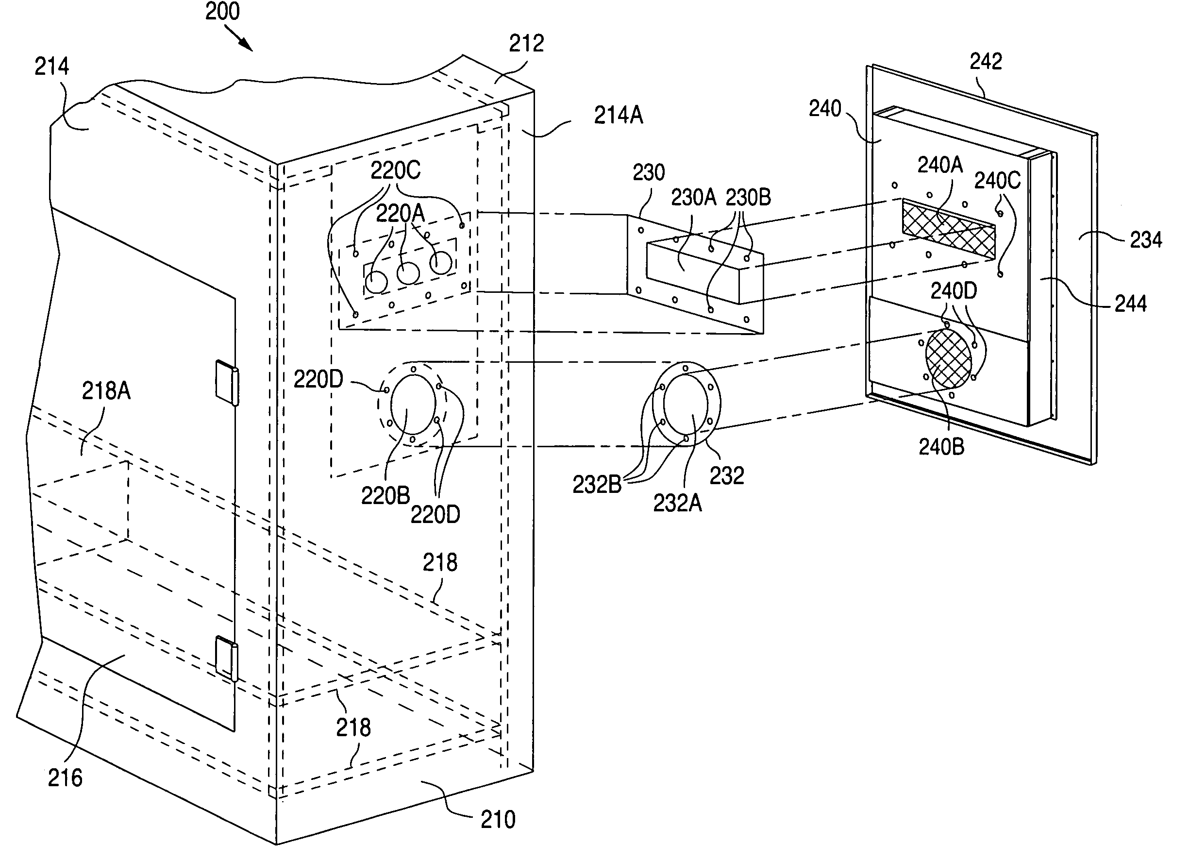
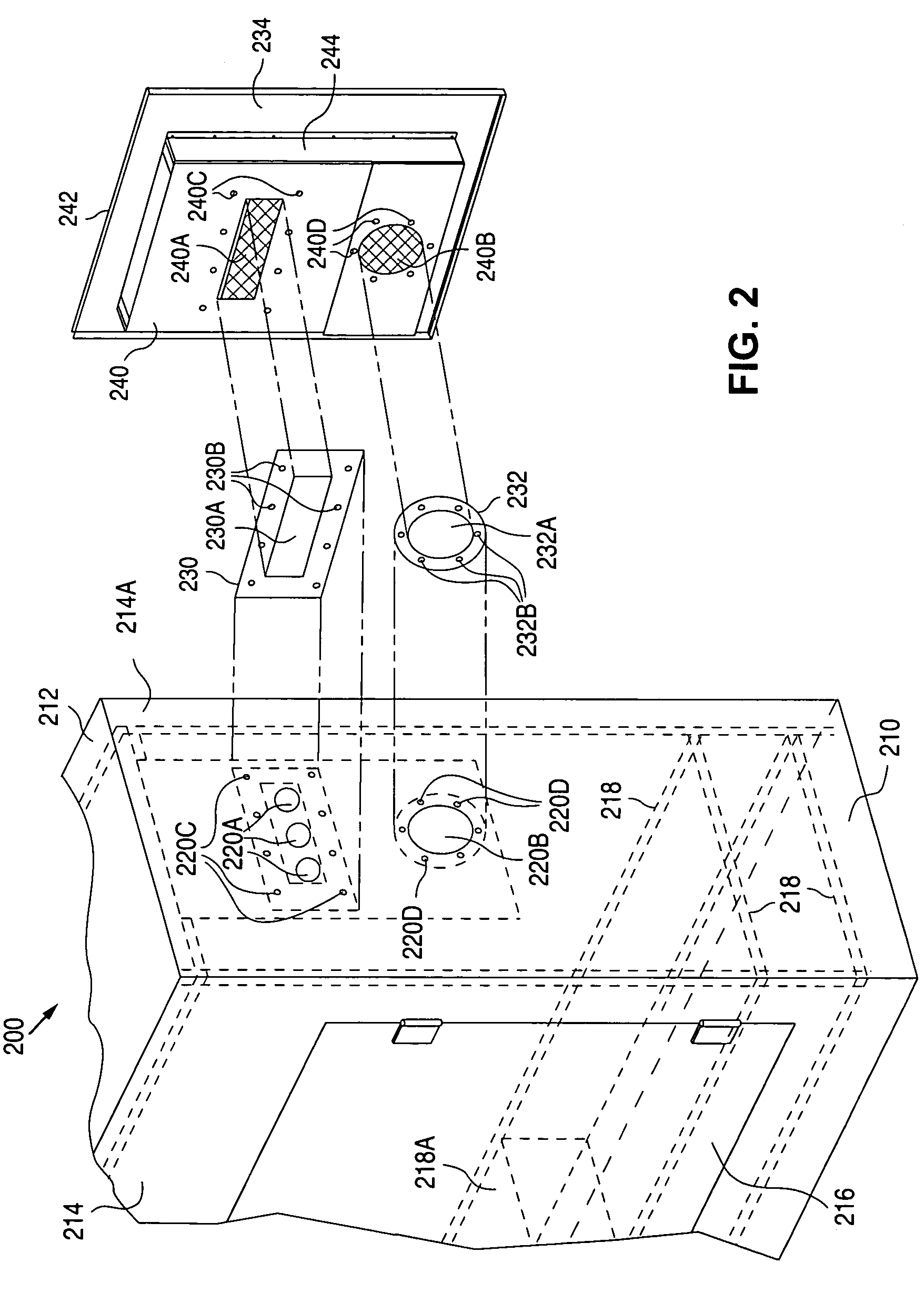
[0025]FIG. 2 shows a perspective view that illustrates an example of an electronics cabinet 200 in accordance with the present invention. As described in greater detail below, the present invention eliminates the difficulties normally associated with retrofitting an existing cabinet to include an air-to-air heat exchanger by attaching the heat exchanger to the exterior of the cabinet.

[0026] As shown in FIG. 2, cabinet 200 includes a bottom surface 210, a top surface 212, a number of side wall surfaces 214, including a mounting side wall surface 214A, that are connected to bottom surface 210 and top surface 212, and a door 216 that is connected to a side wall surface 214 via hinges or other structures that allow an interior of cabinet 200 to be exposed.

[0027] When door 216 is closed, the interior of cabinet 200, as defined by bottom surface 210, top surface 212, side wall surfaces 214, and door 216, becomes an air tight and water tight enclosure. In addition, cabinet 200 includes a...


PUM


Abstract

An air-to-air heat exchanger is simply and easily installed in an electronics cabinet in the field by using a template to form an air exit opening that corresponds with an air inlet opening of the heat exchanger, and an air inlet opening that corresponds with an air exit opening of the heat exchanger. Once the openings have been formed, the heat exchanger is mounted to the outside of the cabinet, such as on a side wall or a door of the cabinet.

Description

BACKGROUND OF THE INVENTION [0001] 1. Field of the Invention [0002] The present invention relates to electronics cabinets and, more particularly, to an electronics cabinet with an air-to-air heat exchanger mounted to the outside of the cabinet. [0003] 2. Description of the Related Art [0004] Telecommunication equipment is commonly housed in electronics cabinets that sit outside in residential and commercial neighborhoods. The cabinets are water tight and air tight to prevent water and dust from entering the cabinets and reducing the useful life of the equipment inside the cabinets. [0005]FIG. 1 shows a perspective view that illustrates a prior-art electronics cabinet 100. As shown in FIG. 1, cabinet 100 includes a base plate 110, a top plate 112, and a number of side walls 114 that are connected to base plate 110 and top plate 112. In addition, cabinet 100 includes a rack 116 that holds telecommunication equipment, and a door 118 that is connected to the side walls 114 via hinges or...

Claims


Application Information

Patent Timeline
Patent Type & Authority Applications(United States)
IPC IPC(8): F24H3/02
CPCH05K9/0041H05K7/206
Inventor FERNANDEZ, PEDRO ANGELGIACOMA, LAWRENCE M.CALANNI, DANIEL J.
Owner TELLABS PETALUMA
Why Eureka
Try Eureka