Sequentially joined-segment coil for rotary electrical machine

a rotary electric machine and segment coil technology, applied in synchronous machines, windings, dynamo-electric components, etc., can solve the problems of increasing the total length of the rotary electric machine, increasing the resistance of the coil, and increasing the length of the coil end, so as to minimize the drop in insulation capability of the conductor segment, reduce the number of rings, and avoid friction between the ends.

Inactive Publication Date: 2006-02-16
DENSO CORP
View PDF38 Cites 64 Cited by
  • Summary
  • Abstract
  • Description
  • Claims
  • Application Information

AI Technical Summary

Benefits of technology

[0014] It is another object of the invention to provide a sequentially joined-segment stator coil for a rotary electric machine which is designed to permit a total length of the electric machine to be decreased and improved cooling capability without increasing coil losses.
[0038] According to the sixth aspect of the invention, there is provided a method of producing the above described segment-joined coil which comprises: (a) preparing a large ring having grooves or holes formed therein at a given pitch in a circumferential direction thereof, a middle ring having grooves or holes formed therein at the same pitch as that of the large ring, and a small ring having groove or holes formed therein at the same pitch as that of the middle ring, the middle ring being arranged inside the large ring, the small ring being arranged inside the middle ring; (b) preparing first and second conductor members for forming the first and second conductor segments, respectively, each of the first and second conductor members including a substantially U-shaped head and a first and a second leg extending form ends of the head; (c) fitting the first legs of the first and second conductor members within the grooves or holes of the middle ring; (d) fitting the second legs of the first conductor members within the grooves or holes of the small ring; (e) fitting the second legs of the second conductor members within the grooves or holes of the large ring; and (f) rotating the large and small rings in the same circumferential direction thereof relative to the middle ring through approximately one magnetic pole pitch to spread the heads of the first and second conductor members in the circumferential direction. This method offers the beneficial effects as described above.

Problems solved by technology

The above sequentially joined-segment stator coil, however, encounters the drawback in that the three heads or turns of the conductor segments disposed in each slot of the core are laid to overlap each other in the axial direction (i.e., a thickness-wise direction) of the core, thus resulting in an increase in length of the coil end (i.e., the projecting end portions of the conductor segments), which leads to an increased total length of a rotary electric machine.
Additionally, the largest outer heads of the conductor segments lead to the outermost side conductor portions and the innermost side conductor portions in the slots, thus requiring a longer length of the segment head-side coil end, which results in increases in coil resistance leading to a coil loss and in ventilating resistance of the coil ends leading to a reduction in cooling capability.

Method used


Image

  • Sequentially joined-segment coil for rotary electrical machine
  • Sequentially joined-segment coil for rotary electrical machine
  • Sequentially joined-segment coil for rotary electrical machine

Examples


second embodiment

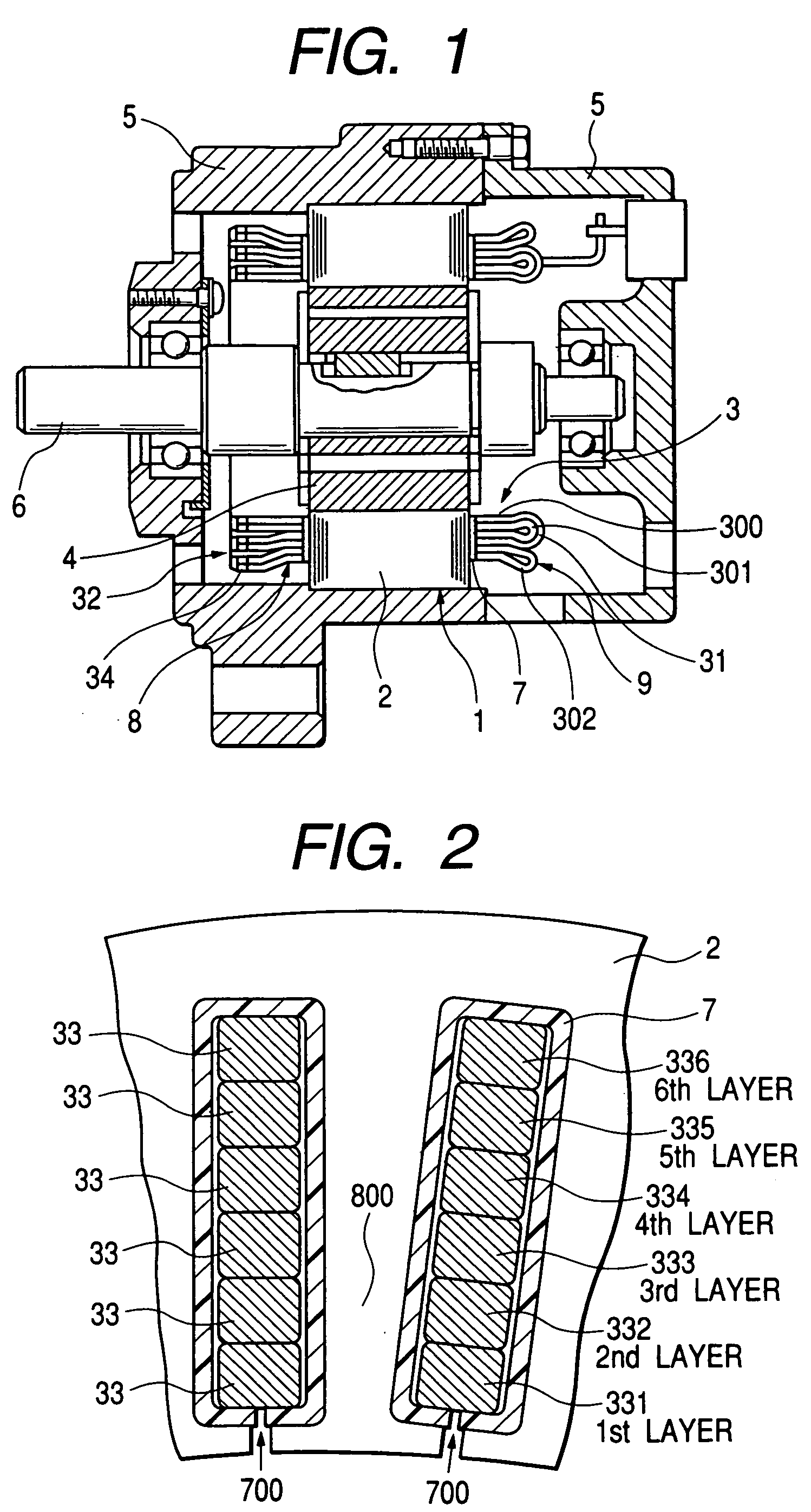
[0122]FIG. 12 is a sectional view which shows the stator 1 in the axial direction thereof in detail. FIG. 13 is a sectional view which shows the stator 1 in the radius direction thereof in detail.

[0123] The stator 1 has formed therein, as described above, three (k=3) same phase slots 351, 352, and 353 for each magnetic pole. A total of p·k·m (p is the number of phases, and m is the number of magnetic poles) slots may be arrayed at equi-angular intervals in the circumferential direction of the core 2. Specifically, the three slots 351 to 353 are arrayed adjacent to each other and have the same phase winding installed therein. In the following discussion, the slots 351, 352, and 353 will also be referred to as a first same phase slot, a second same phase slot, and a third same phase slot, respectively.

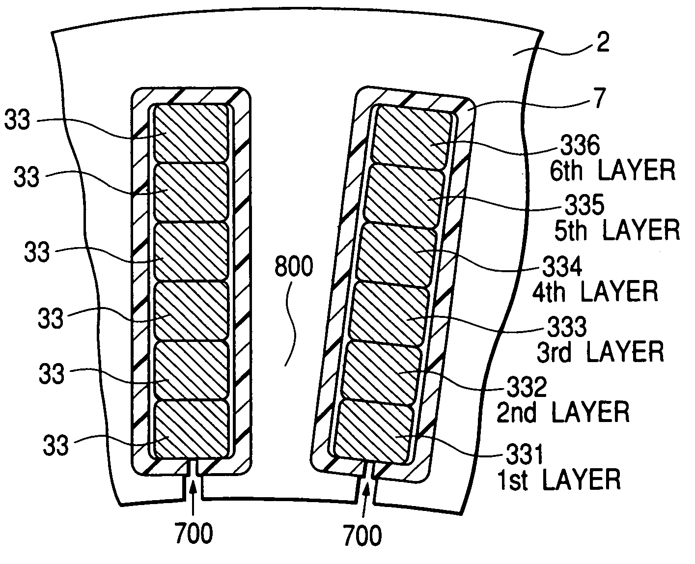
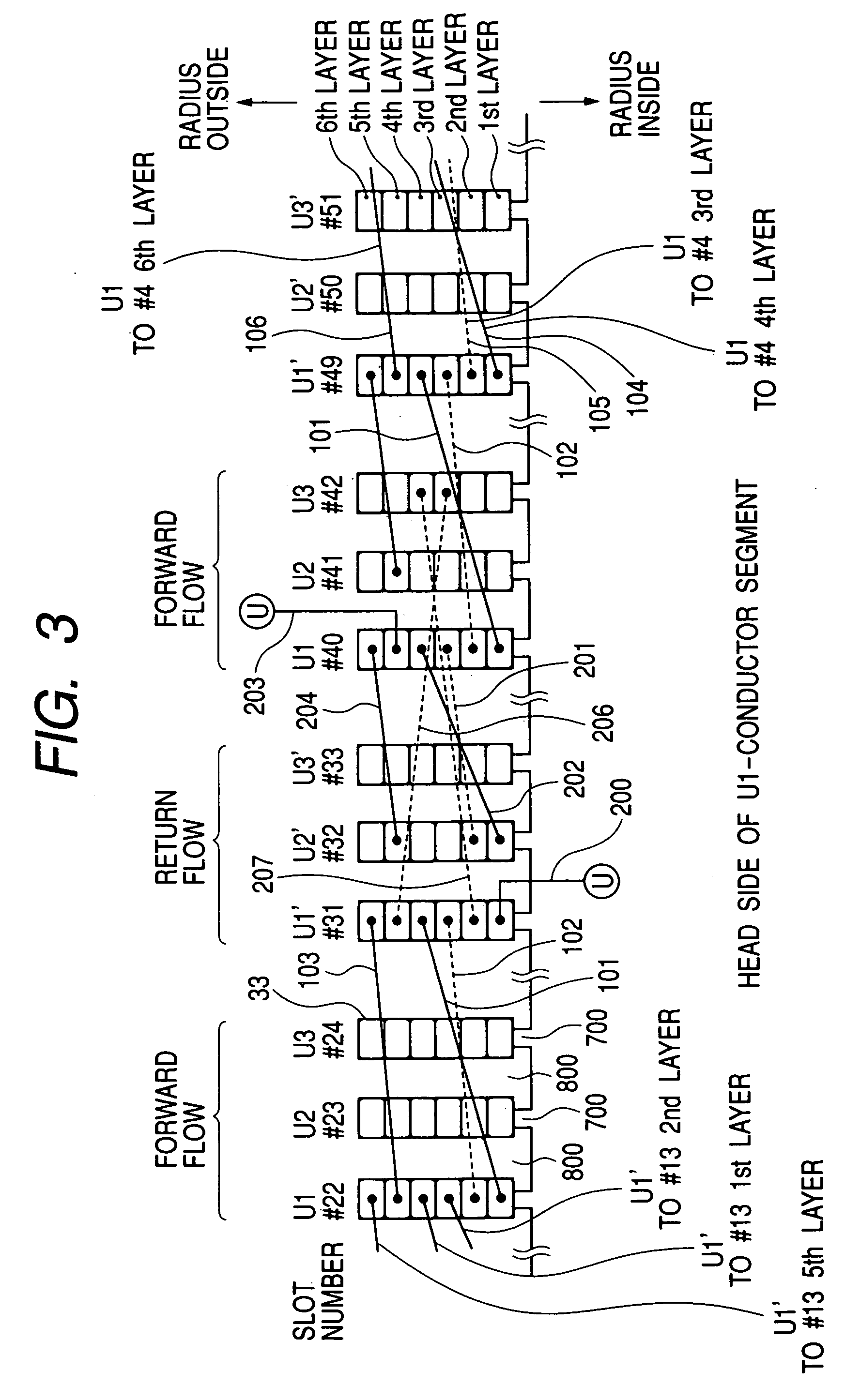
[0124] The six side conductor portions 331 to 336 of the conductor segments 30 are, as described above, arrayed, as illustrated in FIG. 3, in the radius direction of the core 2.

[0125]...

third embodiment

[0158]FIG. 21 shows the conductor segment 30 which includes three types of segments: the large-sized turn conductor segment 300, the small-sized turn conductor segment 301, and the small-sized turn conductor segment 302. The large-sized turn conductor 300 has the side conductor portion 331 disposed at the first layer position and the side conductor portion 334 disposed at the fourth layer position. The small-sized turn conductor segment 301 has the side conductor portion 332 disposed at the second layer position and the side conductor portion 333 disposed at the third layer position. The large-size turn conductor segment 300 and the small-sized turn conductor segment 301 form a circumferentially joined four-conductor leg coil, as will also be referred to as a first coil below. The small-sized turn conductor segment 302 has the side conductor portion 335 disposed at the fifth layer position and the side conductor portion 336 disposed at the sixth layer position and forms a circumfere...


PUM


Abstract

A polyphase sequentially joined-segment coil of a rotary electric machine and a production method thereof are provided. The coil is made up of a plurality of conductor segments joined in series. Each of the conductor segments a head projecting from a stator core, a pair of legs, and a pair of ends projecting from the stator core. The heads are of two types: a large-sized head and a small-sized head extending inside the large-sized head. This structure permits the length of the conductor segments in an axial direction of the core to be decreased and improves cooling capability of the machine and coil losses.

Description

[0001] This is a Division of application Ser. No. 10 / 457,643 filed Jun. 10, 2003. The entire disclosure of the prior application is hereby incorporated by reference herein in its entirety.BACKGROUND OF THE INVENTION [0002] 1. Technical Field of the Invention [0003] The present invention relates generally to a sequentially joined-segment coil of a rotary electric machine and a production method thereof. [0004] 2. Background Art [0005] Sequentially joined-segment stator coils have been proposed which are made by sequentially join ends of conductor segments inserted in slots in a stator core. For instance, Japanese Patent Nos. 3118837 and 3196738, assigned to the same assignee as that of this application, disclose a production method of joining U-shaped conductor segments in sequence to make a stator coil. [0006] The sequentially joined segment stator coil, as taught in the above patents, is made by inserting a pair of legs of each conductor segment into two of slots of a core located ...

Claims


Application Information

Patent Timeline
Patent Type & Authority Applications(United States)
IPC IPC(8): H02K3/00H02K1/00H02K3/12H02K3/28H02K3/50H02K19/22
CPCH02K3/12H02K19/22H02K3/505H02K3/28
Inventor OGAWA, SHINICHIFUKUSHIMA, AKIRA
Owner DENSO CORP
Why Eureka
Try Eureka