Electrical connector with improved preloading structure

a technology of preloading structure and electrical connector, which is applied in the direction of coupling contact member, coupling device connection, two-part coupling device, etc., can solve the problem of detrimental length of electrical stub to signal integrity, and achieve the effect of improving signal integrity and reducing insertion for

Inactive Publication Date: 2008-02-28
HON HAI PRECISION IND CO LTD
View PDF17 Cites 1 Cited by
  • Summary
  • Abstract
  • Description
  • Claims
  • Application Information

AI Technical Summary

Benefits of technology

[0006]One object of the present invention is to provide an electrical connector with lower insertion force and improved signal integrity.

Problems solved by technology

However, in a high speed application, the length of the electrical stub is detrimental to the signal integrity.

Method used


Image

  • Electrical connector with improved preloading structure
  • Electrical connector with improved preloading structure
  • Electrical connector with improved preloading structure

Examples


Embodiment Construction

[0014]Reference will now be made to the drawing figures to describe the present invention in detail.

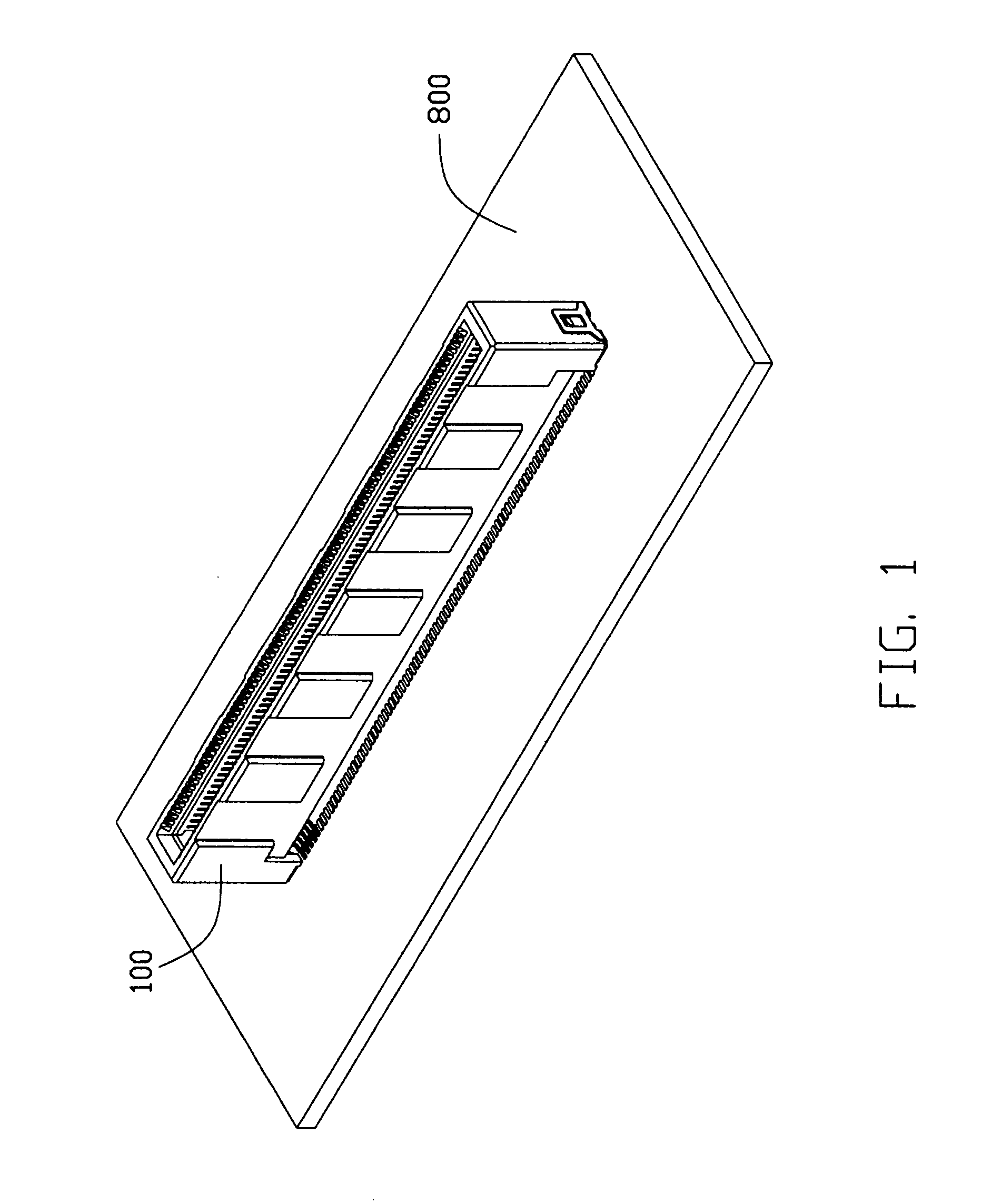
[0015]FIG. 1 shows an electrical connector 100 mounted on a mother board 800 according to the present invention. The electrical connector 100 comprises an insulating housing 20 and two contact inserts 40.

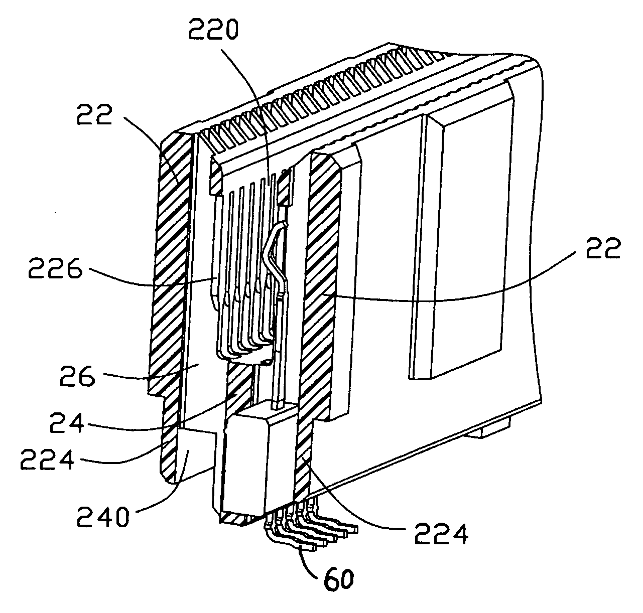
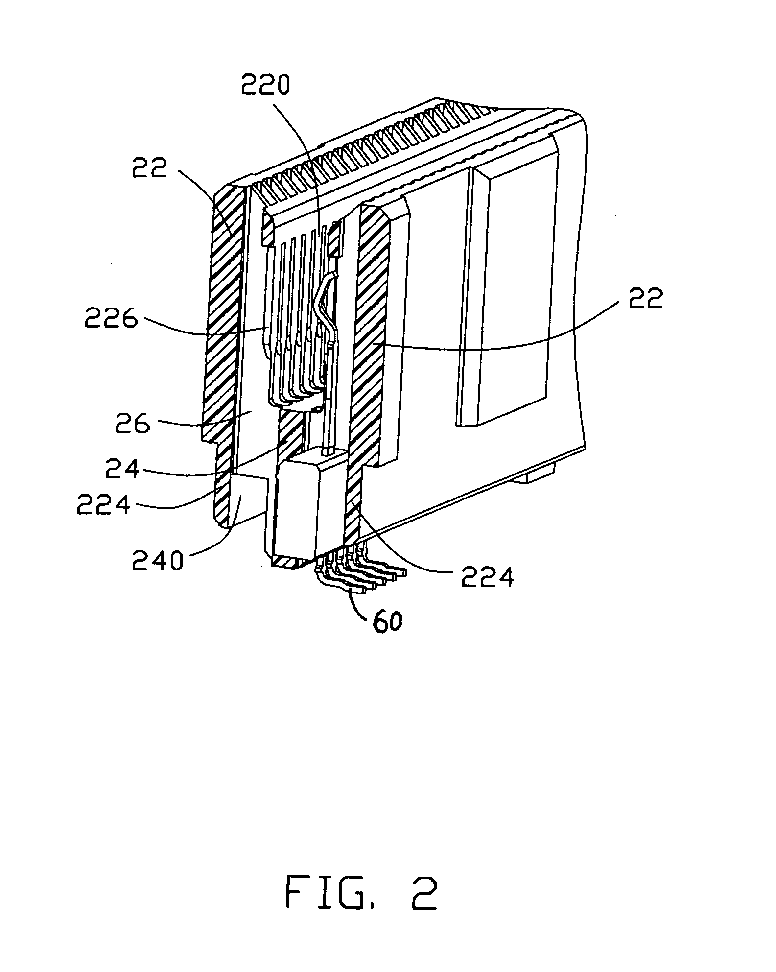
[0016]Referring to FIGS. 2-3, the insulating housing 20 forms a pair of mutual opposite side walls 22 and a bottom wall 24 to define a longitudinal mating slot 220 above the bottom wall 24 for receiving an edge of a daughter card (not shown). The side walls 22 have lower portions 224 aligning with and sandwiching the bottom wall 24. The insulating housing 20 further defines a pair of cavities 240 between lower portions 224 of side wall 22 and the bottom wall 24. Each of the side walls 22 forms a row of contact passageways 26 extending upwardly from corresponding cavity 240 and communicating the receiving slot 220. The contact passageways 26 cut through the side wall 22. The side walls...


PUM


Abstract

An electrical connector (100) for an electrical card includes an insulating housing (20) defining a receiving slot (220) for mating and a number of electrical contacts (60). Each of the electrical contacts has a securing portion for securing the contact in the housing, a contacting portion (66) extending into the receiving slot and a flexible connecting portion (64) connecting the securing portion and the contacting portion. The insulating housing forms a stop portion (226) flexibly biased by said connecting portion when said electrical card is not mated therein.

Description

BACKGROUND OF THE INVENTION[0001]1. Field of the Invention[0002]The present invention relates to an electrical connector having electrical contacts for electrically connecting a daughter card to a mother board, and more particularly, relates to preloading features of the electrical contacts for decreasing an insertion force applied on the electrical component when the electrical component is mated into the electrical connector.[0003]2. Description of the Prior Art[0004]A card edge electrical connector is disclosed with preloading structures in U.S. Pat. No. 5,041,023 issued on Oct. 10, 1995. The electrical connector includes an insulating housing defining a slot for receiving a mating daughter board and a number of electrical contacts lined along two opposite sides of the slot. Each of the electrical contacts includes a securing portion for securing the electrical contact in the housing, a flexible arm extending from the securing portion with a bight interface extending into the slo...

Claims


Application Information

Patent Timeline
Patent Type & Authority Applications(United States)
IPC IPC(8): H01R24/00H01R12/71
CPCH01R12/721H01R13/11
Inventor BIDDLE, GARY E.GILLESPIE, BRIAN J.
Owner HON HAI PRECISION IND CO LTD
Why Eureka
Try Eureka