Microreactor

a micro-reactor and micro-processor technology, applied in the field of micro-reactors, can solve the problem of limited chemical reaction results

Inactive Publication Date: 2006-02-16
YOKOGAWA ELECTRIC CORP
View PDF9 Cites 13 Cited by
  • Summary
  • Abstract
  • Description
  • Claims
  • Application Information

AI Technical Summary

Benefits of technology

[0022] In the microreactor, strength of the ultrasonic wave applied by the ultrasonic wave oscillation section is variable.

Problems solved by technology

However, only limited chemical reactions can be obtained simply by heating depending on the type of fluid.

Method used


Image

  • Microreactor
  • Microreactor
  • Microreactor

Examples


Embodiment Construction

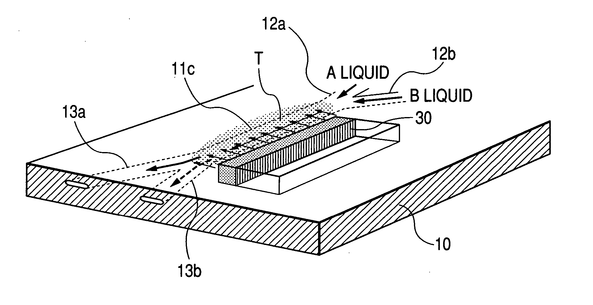
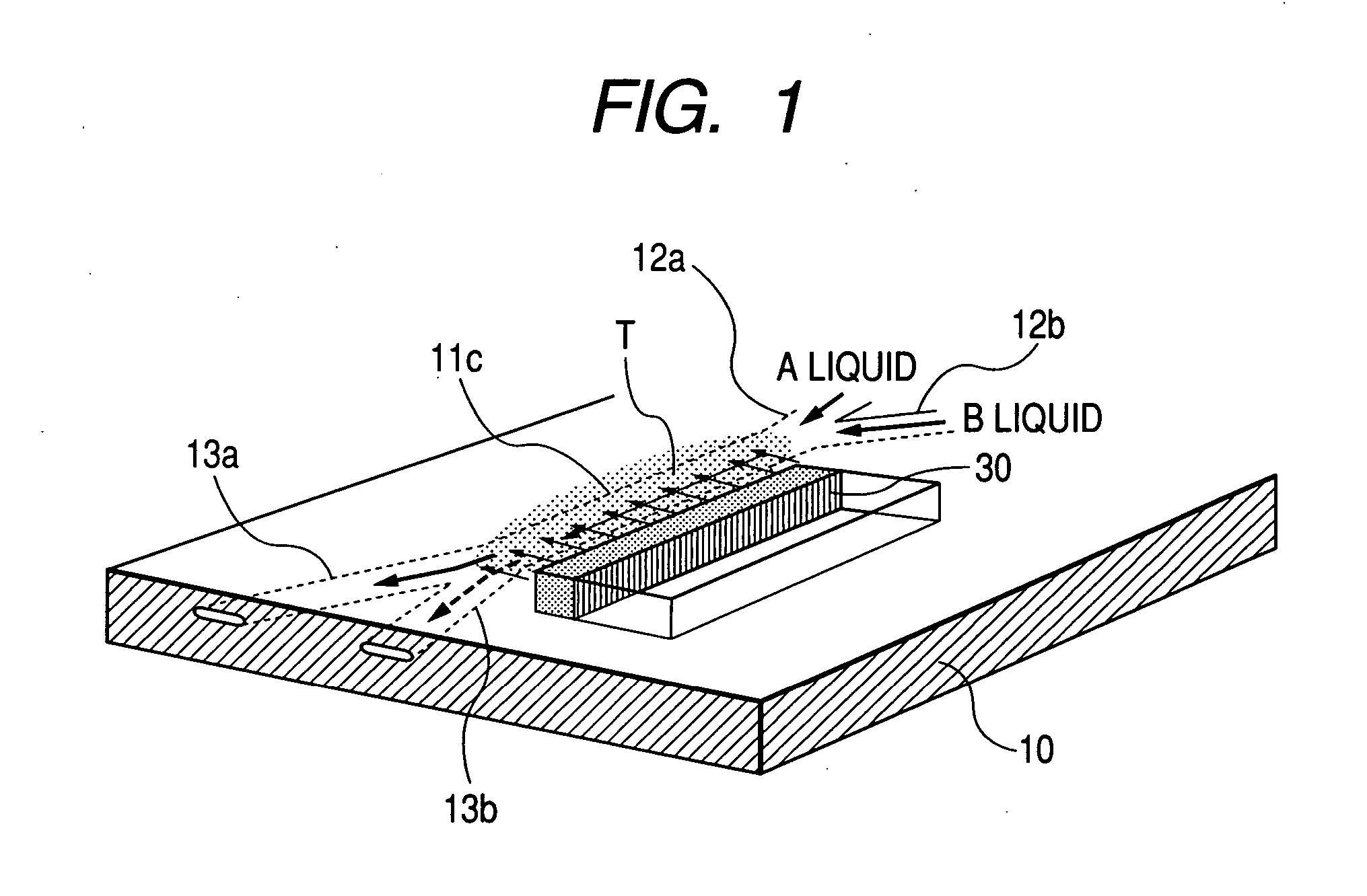
[0029]FIG. 1 shows an embodiment of the invention. Parts similar to those previously described with reference to FIGS. 2A to 2C and FIGS. 3A to 3C are denoted by the same reference numerals in FIG. 1.

[0030] In FIG. 1, A liquid flows into a reactor from a first inflow port 12a, and B liquid flows into the reactor from a second inflow port 12b. These liquids join in a joint flow channel 11c and flow out through outflow ports 13a and 13b.

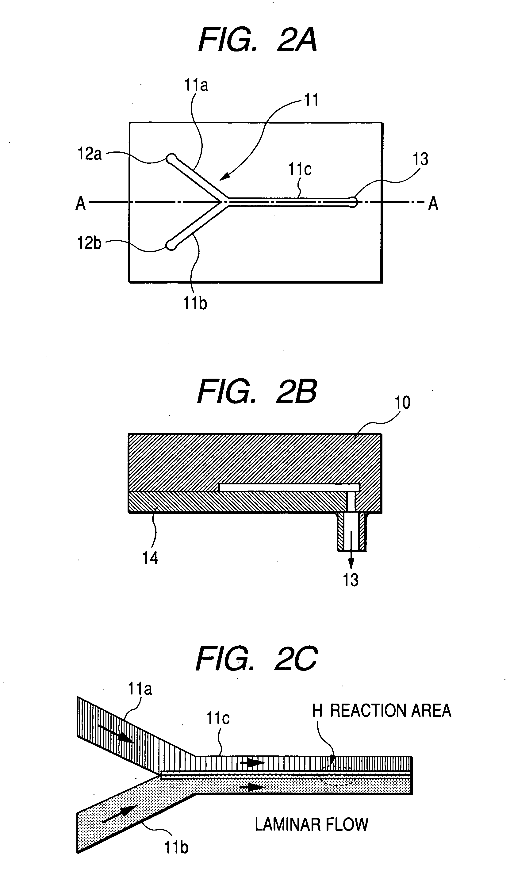
[0031] Although not shown, a second substrate similar to that previously described with reference to FIGS. 2A to 2C in the related art example is formed on the side where the joint flow channel 11c of a first substrate 10 is formed, and covers the inflow ports 12a and 12b and the outflow ports 13a and 13b.

[0032] Numeral 30 denotes an ultrasonic wave oscillation element disposed along the joint flow channel 11c for applying an ultrasonic wave T in a direction at right angles to the flow direction of the A liquid and the B liquid flowing through the j...


PUM

PropertyMeasurementUnit
diameteraaaaaaaaaa
thicknessaaaaaaaaaa
thicknessaaaaaaaaaa

Abstract

A microreactor has a plurality of flow channels and a joint flow channel where the plurality of flow channels are joined. Fluids flowing through the plurality of flow channels join in the joint flow channel to react with each other. The microreactor further has an ultrasonic wave oscillation section which applies an ultrasonic wave to the joint flow channel.

Description

CROSS-REFERENCE TO RELATED APPLICATIONS [0001] This application is based upon and claims the benefit of priority from the prior Japanese Patent Applications No. 2004-232882, filed on Aug. 10, 2004, the entire contents of which are incorporated herein by reference. BACKGROUND OF THE INVENTION [0002] 1. Field of the Invention [0003] In recent years, researches on controlling creation of super molecules making the most of a photocalytic chemical reaction and a photo-enzyme chemical reaction using laser light and separation and purification of biochemical substances of an enzyme, a protein, etc., using a photoreaction have advanced. Application to state analysis such as spectral analysis using plasma generated by laser light has also advanced. The invention relates to a microreactor as a reaction vessel used in such a field. [0004] 2. Description of the Related Art [0005] The microreactor is a very small-sized reaction vessel and is formed of a substance whose physico-chemical character...

Claims


Application Information

Patent Timeline
Patent Type & Authority Applications(United States)
IPC IPC(8): B06B1/00B32B27/04
CPCB01F11/025B01F13/0059B01J19/0093B01L3/5027B01J2219/00835B01J2219/00932B01J2219/00936B01J2219/00783B01F31/841B01F33/30
Inventor MIURA, AKIRAWADA, MORIOYAKIHARA, TSUYOSHIKOBAYASHI, SHINJI
Owner YOKOGAWA ELECTRIC CORP
Why Eureka
Try Eureka