Power supply and control method therefor

a technology of power supply and control method, which is applied in the direction of portable application adaption, electrical generator, sustainable building, etc., to achieve the effect of stably providing electric power

Inactive Publication Date: 2006-02-16
HITACHI LTD
View PDF5 Cites 27 Cited by
  • Summary
  • Abstract
  • Description
  • Claims
  • Application Information

AI Technical Summary

Benefits of technology

[0008] The power supply as a whole can stably supply electric power required by the load even for

Problems solved by technology

The fuel cells have a problem that because a fuel cell is a power generator which converts chemical energy into electric power, it takes time from when t

Method used


Image

  • Power supply and control method therefor
  • Power supply and control method therefor
  • Power supply and control method therefor

Examples


first embodiment

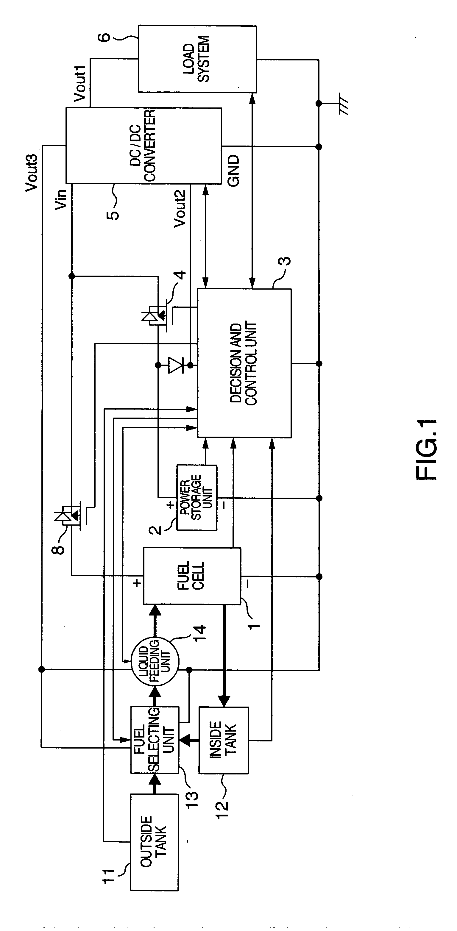
[0030] A first embodiment of the present invention is described with reference to FIG. 1. FIG. 1 is a block diagram schematically showing a structure of the power supply unit and connections of power lines and signal lines.

[0031] In the structure of this embodiment, there are provided two power supplies, that is, a fuel cell 1 and a power storage unit 2, a blocking diode for backflow prevention and a discharge switch 8 on the fuel cell 1 side, and a discharging diode and a charging switch 4 for controlling charging ON / OFF on the power storage unit side. In FIG. 1 the diode and charging switch 4 are connected to the positive side of the power storage unit 2, but they may be connected to the negative side of the power storage unit 2. For this purpose, a switching element, such as a P-channel MOF FET or an N-channel MOS FET, may be used, which provides a better efficiency in conducting a large current than in the case where only the diode is used.

[0032] The switching element is contr...

second embodiment

[0101] Description will be made of an embodiment in the case where two outside fuel tanks 11 are used.

[0102] In comparison with the first embodiment, a significant change lies in the structure of the fuel-related block. FIG. 10 shows the structure in the second embodiment. In the structure in FIG. 10, there are provided two kinds of fuel storages: two outside fuel tanks 11 and one inside fuel tank 12. The outside fuel tanks 11 are provided with a user-detachable remaining amount detecting unit for detecting a remaining amount of fuel. The inside fuel tank 12 is built in the fuel cell system and cannot be detached, is smaller than the outside fuel tanks 11, and can store fuel that has passed through the fuel cell 1.

[0103] The fuel selecting unit 13 can switch over the flow paths of the two outside fuel tanks 11 and the inside fuel tank 12 to select any one state among the two-or-more-usable state, one-usable state, and none-usable state. When using one tank, the fuel storage having...

third embodiment

[0106]FIG. 11 shows a third embodiment of the present invention. The fuel cell system according to this embodiment has a structure that the portion indicated by a broken line is incorporated in the load system main body, and the portion other than the broken-line-enclosed region is a battery pack. The feature of this embodiment lies in specifications for the interface to connect between the load system 6 and the fuel cell 1. In addition to a power terminal of the fuel cell 1 and power terminals to the auxiliary devices, the remaining amount signal terminals of the outside fuel tank 11 and the inside fuel tank 12, the interface includes control signal terminals to the auxiliary devices, state signal terminals, such as temperature, of the fuel cell 1, and identification signal terminals of the fuel cell 1 and the power storage unit 2.


PUM


Abstract

A power supply unit in a hybrid structure of a fuel cell and a power storage unit and a control method for the power supply unit, in which a small-size light-weight power storage unit is used and chances of incomplete functioning have been eliminated. In addition to the downsizing of the power storage unit and a reduction of the system price, it also becomes possible to start the fuel cell at high speed and raise the fuel cell temperature quickly, monitor output and remaining mounts of fuel and power, and take measures against fluctuations of output, and provides immediate availability of portable devices like the ones using a conventional secondary cell.

Description

BACKGROUND OF THE INVENTION [0001] The present invention relates to a power supply unit using a fuel cell and a control method therefor. [0002] Fuel cells are recently drawing attention as an electric power generator for its environment-friendliness and generally higher power generation efficiency than diesel-engine or gas-turbine generators. [0003] However, unlike other types of power generators, the fuel cell, which generates power by chemical reaction, takes time before it starts working fully and is inferior in startability to other power generators. [0004] JP-A-2004-66917 contains description pertaining to solving the problem of the startability in the case of the solid oxide fuel cell, more specifically, it states that a fuel cell and a secondary cell are provided, excess power is stored in the secondary battery, and stored power is used when starting the fuel cell, in an attempt to eliminate the problem of startability. SUMMARY OF THE INVENTION [0005] The fuel cells have a pr...

Claims


Application Information

Patent Timeline
IPC IPC(8): H01M12/00
CPCH01M8/04223Y02B90/18H01M8/04365H01M8/04559H01M8/04567H01M8/04604H01M8/04731H01M8/0494H01M8/04947H01M8/04955H01M16/00H01M16/006H01M2250/30H02M3/158H02M2001/009Y02E60/50H01M8/04268H01M8/04225H01M8/04228H01M8/04302H01M8/04303H02M1/009Y02B90/10Y02E60/10
Inventor NORIMATSU, YASUAKIKANOUDA, AKIHIKOKIKUCHI, MUTSUMI
Owner HITACHI LTD
Why Eureka
Try Eureka