Fuel cell system, electrical apparatus and method for recovering water formed in fuel cell system

a fuel cell and electrical equipment technology, applied in electrochemical generators, sustainable buildings, separation processes, etc., can solve the problems of lithium-ion cells not meeting the requirements of driving power supplies, lithium-ion cells become insufficient to meet the requirements of battery power supply requirements, and invite malfunctions or defects in the apparatus, etc., to achieve convenient and reliable recovery of water, improve the effect of performan

Inactive Publication Date: 2006-02-16
FUJITSU LTD
View PDF11 Cites 20 Cited by
  • Summary
  • Abstract
  • Description
  • Claims
  • Application Information

AI Technical Summary

Benefits of technology

[0016] In the fuel cell system, an electric power generation reaction utilizing the fuel occurs to thereby generate electric power in the fuel-cell power generation part. The generated electricity (electric power) is utilized as driving force for, for example, electrical apparatuses. The electric power generation reaction also yields water. The water vaporizes to form water vapor and diffuses into a gas. The gas is heat-exchanged, and the water vapor contained in the gas condenses to form water droplets inside the heat-exchange chamber. This prevents the water vapor contained in the gas from condensing outside the heat-exchange chamber and from causing condensation. The water droplets formed in the heat-exchange chamber remain inside thereof and do not leak out. Thus, the fuel cell system is substantially free from, for example, deteriorated performance and uncomfortable feeling in use caused by the water, can easily and reliably recover the water and can be handled satisfactorily.
[0017] Preferably, at least part of a wall of the heat-exchange chamber contains a porous membrane having continuous holes and / or pores communicating one surface of the wall with the other surface. In this configuration, the heat-exchange chamber isolates the gas containing the water vapor from outside by the action of the porous membrane, is hermetically sealed to such an extent as to prevent the water from leaking out macroscopically and keeps the inside temperature at the dew point of the water or below by the action of the porous membrane. This effectively prevents the condensation of the water outside the fuel cell system. In addition, the electric power generation is prevented from decreasing, since oxygen can permeate the porous membrane.

Problems solved by technology

Improvements in the performances of the lithium-ion cells, however, have some limitations, the lithium-ion cells become to fail to satisfactorily meet the requirements as the drive power supplies of such high-function portable information-processing apparatuses.
However, such water coming into the inside of an apparatus to be powered by the fuel cells may invite malfunctions or defects in the apparatus and uncomfortable wet conditions to a user.
This technique, however, does not effectively prevent the water from leaking out from the fuel cell, which gives uncomfortable wet conditions to users.

Method used


Image

  • Fuel cell system, electrical apparatus and method for recovering water formed in fuel cell system
  • Fuel cell system, electrical apparatus and method for recovering water formed in fuel cell system
  • Fuel cell system, electrical apparatus and method for recovering water formed in fuel cell system

Examples


example 1

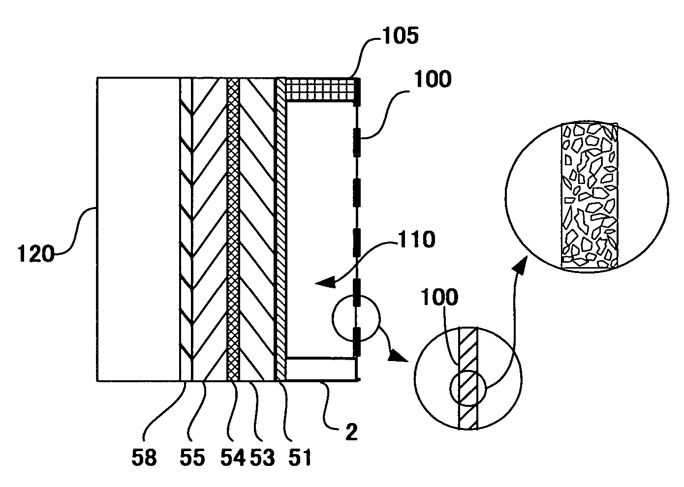
[0186] An example of the fuel cell system of the present invention will be illustrated with reference to the drawings. With reference to FIG. 1, the fuel cell system comprises a fuel-cell power generation part 50, a heat-exchange chamber 110 and a fuel chamber 120. The fuel cell according to Example 1 was attached to the mobile phone and the mobile phone cradle shown in FIGS. 14 through 17.

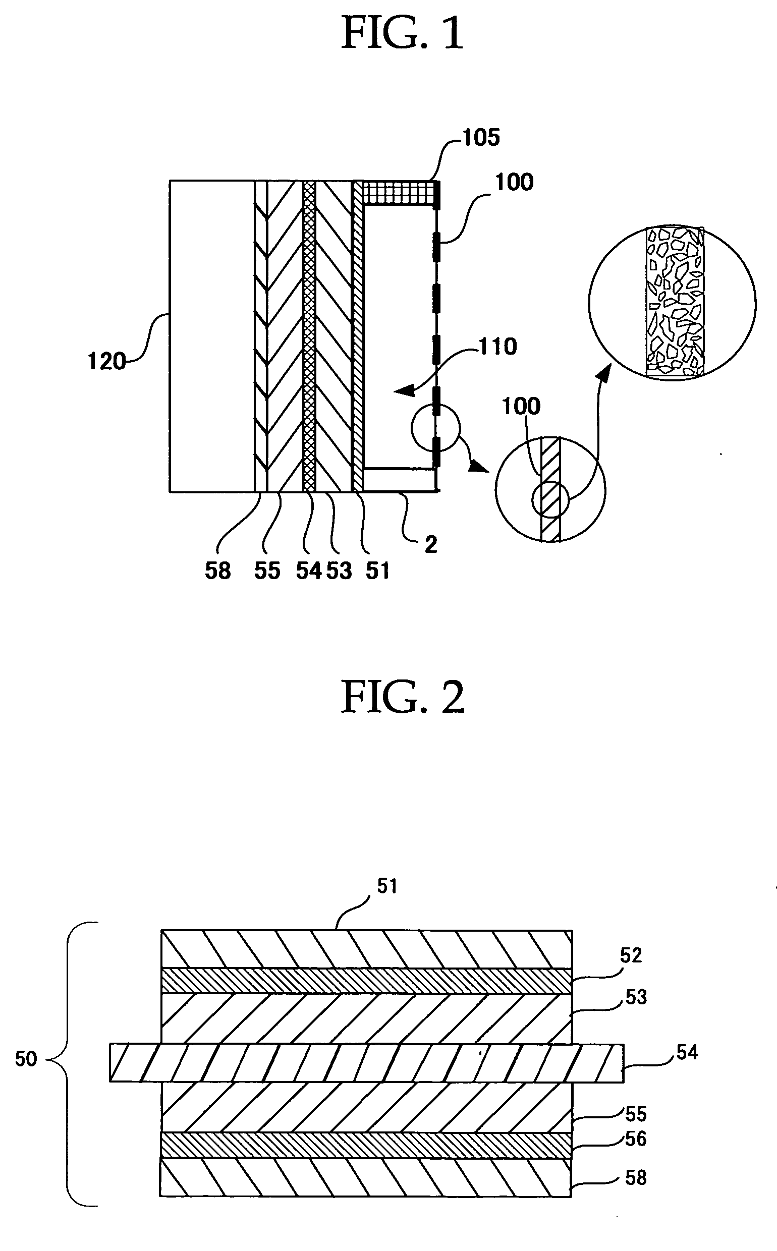
[0187] In FIG. 1, the fuel-cell power generation part 50 is shown as a laminated body having an air-electrode collector 51, an air electrode (cathode) 53, a solid electrolyte 54, a fuel electrode (anode) 55, and a fuel-electrode collector 58.

[0188] The fuel-cell power generation part 50 shown in FIG. 2 had an air-electrode collector 51, a carbon paper 52, an air electrode (cathode) 53, a solid electrolyte 54, a fuel electrode (anode) 55, a carbon paper 56 and a fuel-electrode collector 58 laminated in this order. The fuel-cell power generation part 50 was a direct methanol fuel cell.

[0189] In t...

example 2

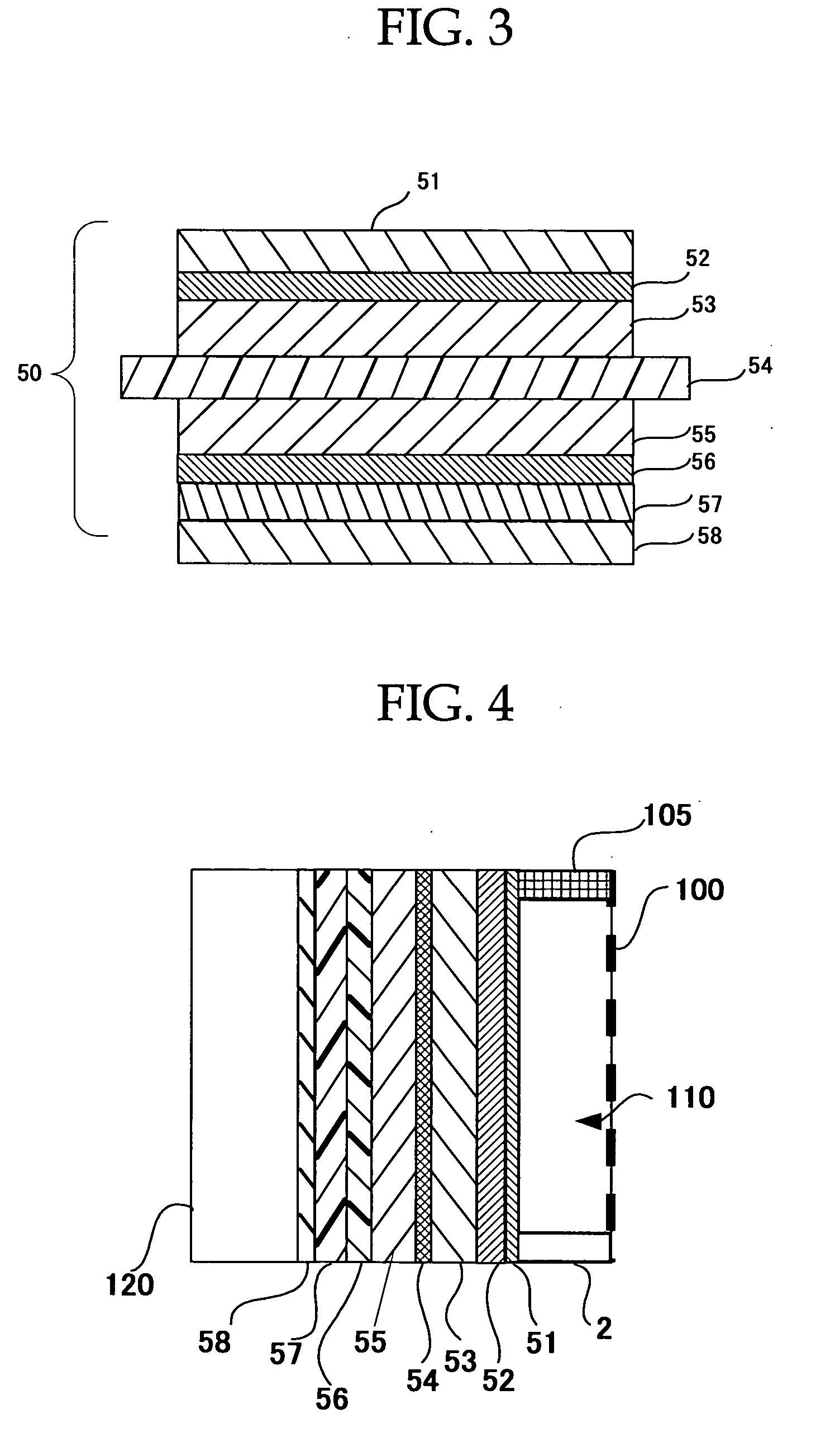
[0198] A fuel cell system was prepared so as to have the configuration of Example 1, except for further comprising a shutter 57 arranged between the carbon paper 56 and the fuel electrode collector 58 in the fuel-cell power generation part 50. More specifically, the fuel cell system according to Example 2 had a configuration shown in FIG. 4 and was prepared by the procedure of Example 1, except for using a fuel-cell power generation part shown in FIG. 3. The fuel cell system according to Example 2 exhibited the same operation and advantages as in the fuel cell system according to Example 1.

example 3

[0199] A fuel cell system was prepared so as to have the configuration of Example 1, except for further comprising dendritic driving channles (water courses 101) (FIG. 5) on a surface of the porous membrane 100 exposed to the heat-exchange chamber by photolithography.

[0200] The driving channels had a dendritic shape comprising three main lines extending from above and a multiplicity of branches obliquely extending to the main lines from above. The fuel cell system according to Example 3 exhibited similar operation and advantages to the fuel cell system according to Example 1. In addition, this fuel cell system could further efficiently absorb and fix (remove) the water formed as a result of condensation in the heat-exchange chamber 110, since the water efficiently fell along the driving channels into water-absorptive member 2.


PUM

PropertyMeasurementUnit
porosityaaaaaaaaaa
porosityaaaaaaaaaa
porosityaaaaaaaaaa

Abstract

A fuel cell system includes a fuel-cell power generation part containing a fuel electrode, a solid electrolyte and an air electrode, and a heat-exchange chamber configured to cool a gas emitted from the fuel-cell power generation part to thereby form water. A power generation reaction using a fuel yields electric power and water in the fuel-cell power generation part. The electric power is utilized as driving force typically for an electrical apparatus. A gas containing the water as vapor undergoes heat exchange and condensation to thereby form water in the heat-exchange chamber. The formed water remains inside the heat-exchange chamber without leaking out. The fuel cell system is free from deteriorated performance and uncomfortable feeling in use and can easily and reliably recover the water.

Description

CROSS-REFERENCE TO RELATED APPLICATIONS [0001] This application is based upon and claims the benefits of the priority from the prior Japanese Patent Application No. 2004-235980, filed on Aug. 13, 2004, the entire contents of which are incorporated herein by reference. BACKGROUND OF THE INVENTION [0002] 1. Field of the Invention [0003] The present invention relates to techniques for easily and reliably absorbing water formed in a fuel cell system. More specifically, it relates to a fuel cell system and a method for recovering water formed in the fuel cell system, and to an electrical apparatus having the fuel cell system. [0004] 2. Description of the Related Art [0005] Portable information-processing apparatuses such as mobile phones and portable computer systems (notebook personal computers) have been more and more miniaturized, reduced in weight, increased in speed and improved in function. Thus, cells serving as power supplies thereof have been more and more miniaturized, reduced ...

Claims


Application Information

Patent Timeline
Patent Type & Authority Applications(United States)
IPC IPC(8): H01M8/04
CPCB01D5/0003H01M8/04067H01M8/04164Y02B90/18H01M2008/1095H01M2250/30Y02E60/50H01M8/04291Y02B90/10
Inventor TAKEI, FUMIO
Owner FUJITSU LTD
Why Eureka
Try Eureka