Fuel cell system, electrical apparatus and method for recovering water formed in fuel cell system
a fuel cell and electrical equipment technology, applied in electrochemical generators, separation processes, sustainable buildings, etc., can solve the problems of lithium-ion cells not meeting the requirements of driving power supplies, lithium-ion cells become insufficient to meet the requirements of battery power supply requirements, and invite malfunctions or defects in the apparatus, etc., to achieve convenient and reliable recovery of water, improve the effect of performan
- Summary
- Abstract
- Description
- Claims
- Application Information
AI Technical Summary
Benefits of technology
Problems solved by technology
Method used
Image
Examples
example 1
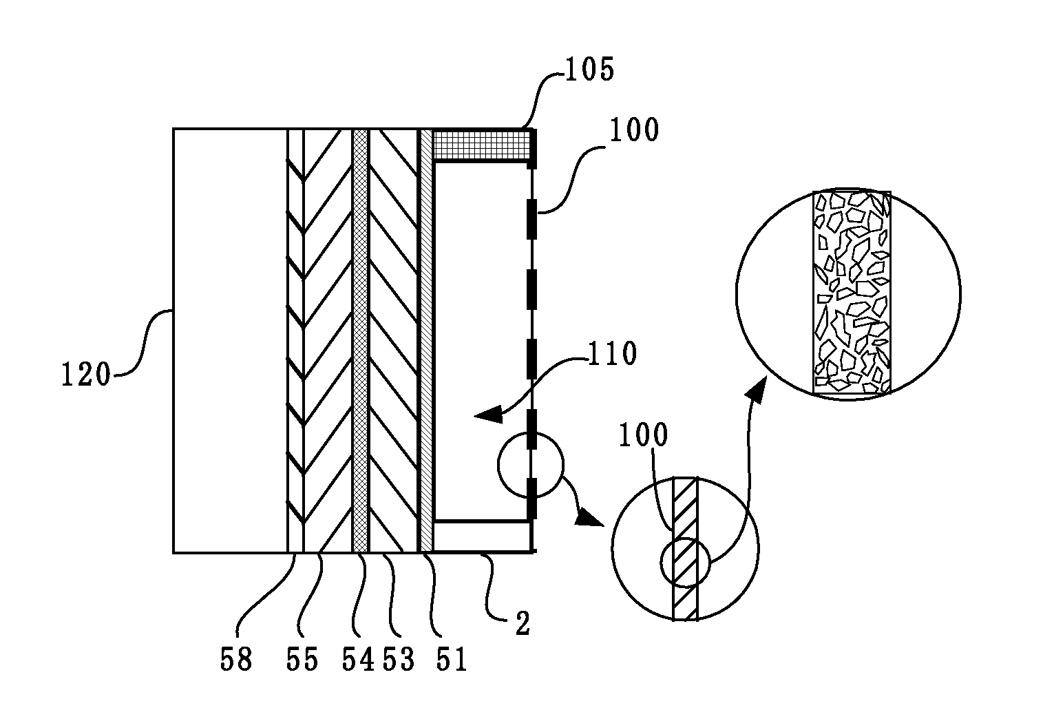
[0186]An example of the fuel cell system of the present invention will be illustrated with reference to the drawings. With reference to FIG. 1, the fuel cell system comprises a fuel-cell power generation part 50, a heat-exchange chamber 110 and a fuel chamber 120. The fuel cell according to Example 1 was attached to the mobile phone and the mobile phone cradle shown in FIGS. 14 through 17.
[0187]In FIG. 1, the fuel-cell power generation part 50 is shown as a laminated body having an air-electrode collector 51, an air electrode (cathode) 53, a solid electrolyte 54, a fuel electrode (anode) 55, and a fuel-electrode collector 58.
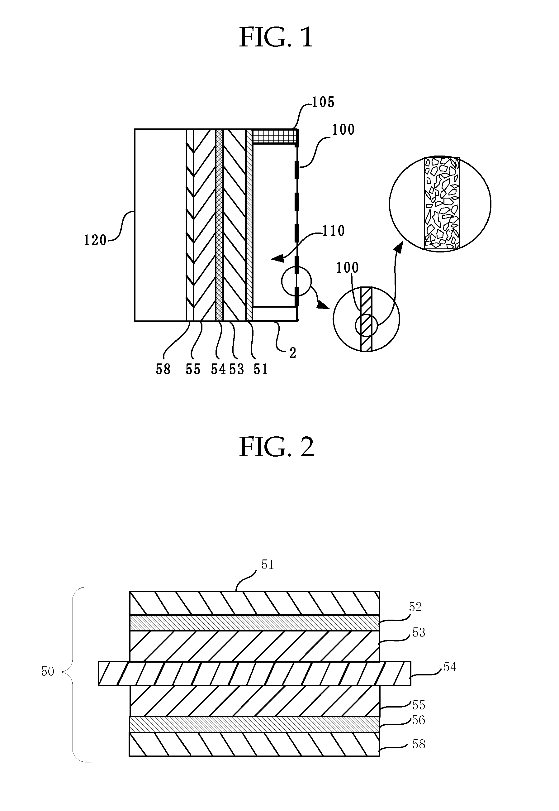
[0188]The fuel-cell power generation part 50 shown in FIG. 2 had an air-electrode collector 51, a carbon paper 52, an air electrode (cathode) 53, a solid electrolyte 54, a fuel electrode (anode) 55, a carbon paper 56 and a fuel-electrode collector 58 laminated in this order. The fuel-cell power generation part 50 was a direct methanol fuel cell.
[0189]In this exa...
example 2
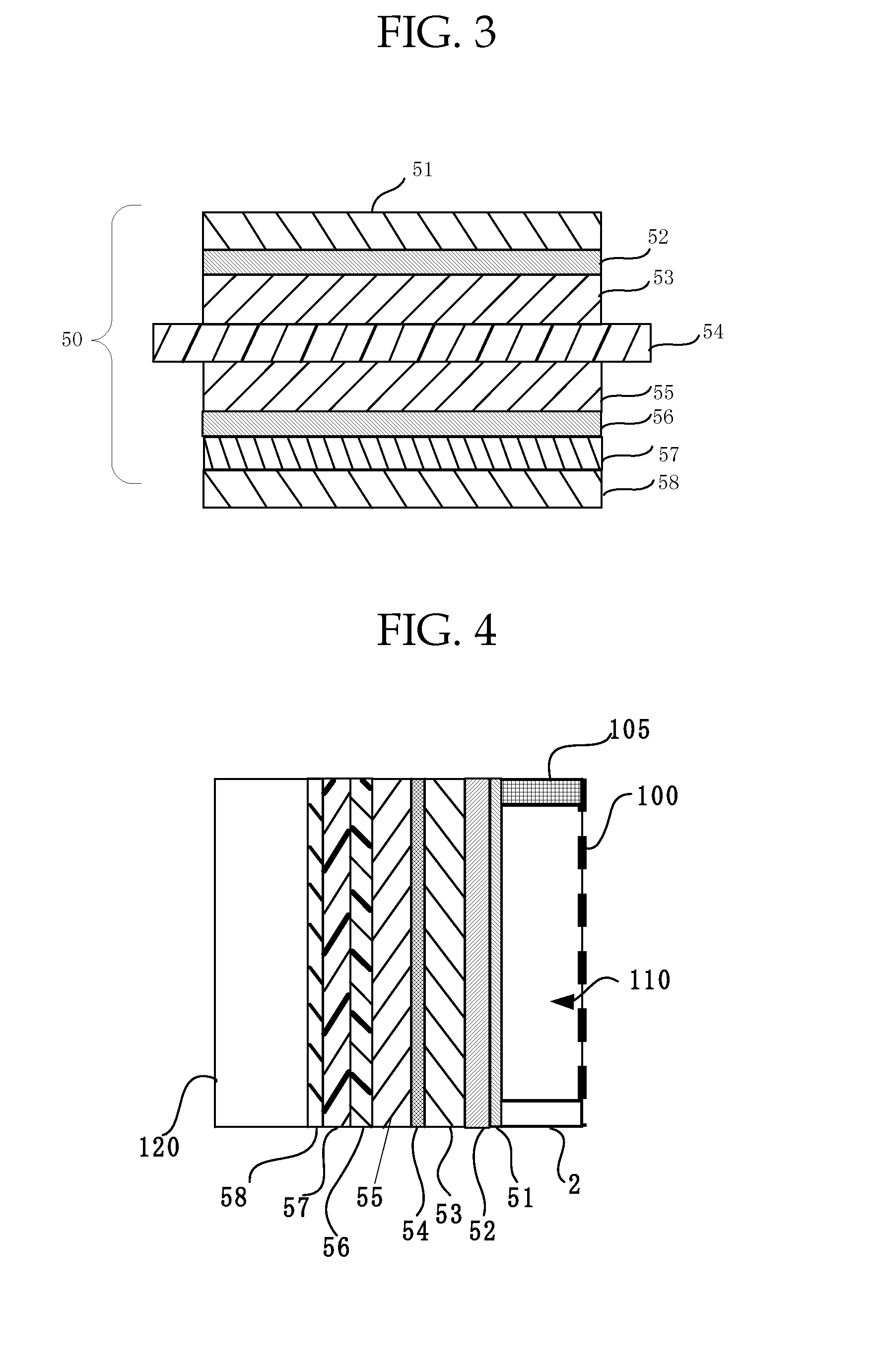
[0198]A fuel cell system was prepared so as to have the configuration of Example 1, except for further comprising a shutter 57 arranged between the carbon paper 56 and the fuel electrode collector 58 in the fuel-cell power generation part 50. More specifically, the fuel cell system according to Example 2 had a configuration shown in FIG. 4 and was prepared by the procedure of Example 1, except for using a fuel-cell power generation part shown in FIG. 3. The fuel cell system according to Example 2 exhibited the same operation and advantages as in the fuel cell system according to Example 1.
example 3
[0199]A fuel cell system was prepared so as to have the configuration of Example 1, except for further comprising dendritic driving channels (water courses 101) (FIG. 5) on a surface of the porous membrane 100 exposed to the heat-exchange chamber by photolithography.
[0200]The driving channels had a dendritic shape comprising three main lines extending from above and a multiplicity of branches obliquely extending to the main lines from above. The fuel cell system according to Example 3 exhibited similar operation and advantages to the fuel cell system according to Example 1. In addition, this fuel cell system could further efficiently absorb and fix (remove) the water formed as a result of condensation in the heat-exchange chamber 110, since the water efficiently fell along the driving channels into water-absorptive member 2.
PUM
| Property | Measurement | Unit |
|---|---|---|
| porosity | aaaaa | aaaaa |
| pore diameter | aaaaa | aaaaa |
| distance | aaaaa | aaaaa |
Abstract
Description
Claims
Application Information
 - R&D
- Intellectual Property
- Life Sciences
- Materials
- Tech Scout
- Unparalleled Data Quality
- Higher Quality Content
- 60% Fewer Hallucinations
Browse by: Latest US Patents, China's latest patents, Technical Efficacy Thesaurus, Application Domain, Technology Topic, Popular Technical Reports.
© 2025 PatSnap. All rights reserved.Legal|Privacy policy|Modern Slavery Act Transparency Statement|Sitemap|About US| Contact US: help@patsnap.com


