Ring light guide

a technology of ring light and guide, which is applied in the direction of optical waveguide light guide, camera body details, instruments, etc., can solve the problems of complex and costly conventional ring light system, particularly troublesome arrangement for close-up imaging, undesirable shadow and overexposure effects

Inactive Publication Date: 2006-02-23
CARESTREAM HEALTH INC
View PDF5 Cites 40 Cited by
  • Summary
  • Abstract
  • Description
  • Claims
  • Application Information

AI Technical Summary

Benefits of technology

[0017] It is another advantage of the present invention that it allows the design of a ring illuminator that utilizes the built-in light output and light sensing components of a camera, minimizing or eliminating the need to make manual adjustments to camera operation to compensate for ring lighting use.

Problems solved by technology

While this may be acceptable for the bulk of imaging applications, this arrangement is particularly troublesome for close-up imaging, such as in dental imaging and imaging of small objects in near distance.
In close-up camera work, the conventional flash illumination arrangement often results in undesirable shadow and overexposure effects.
While such active ring light devices provide improved illumination for many types of close-up photography applications, there are some drawbacks.
Because of this, a conventional ring light system can be complex and costly.
Another key disadvantage of such active ring light solutions relates to the suitability of the illumination provided to any particular camera.
Devices that substitute other types of light sources for flash illumination may indeed minimize shadows and other effects but, at the same time, may compromise image quality, particularly with respect to color balance.
Other drawbacks with many conventional devices include excessive size and weight.
While these solutions may provide light with spectral characteristics that are better suited to the individual camera type, drawbacks of complexity, cost, size, and usability remain.

Method used


Image

  • Ring light guide
  • Ring light guide
  • Ring light guide

Examples


Embodiment Construction

[0033] The present description will be directed in particular to elements forming part of, or in cooperation more directly with the apparatus in accordance with the present invention. It is to be understood that elements not specifically shown or described may take various forms well known to those skilled in the art.

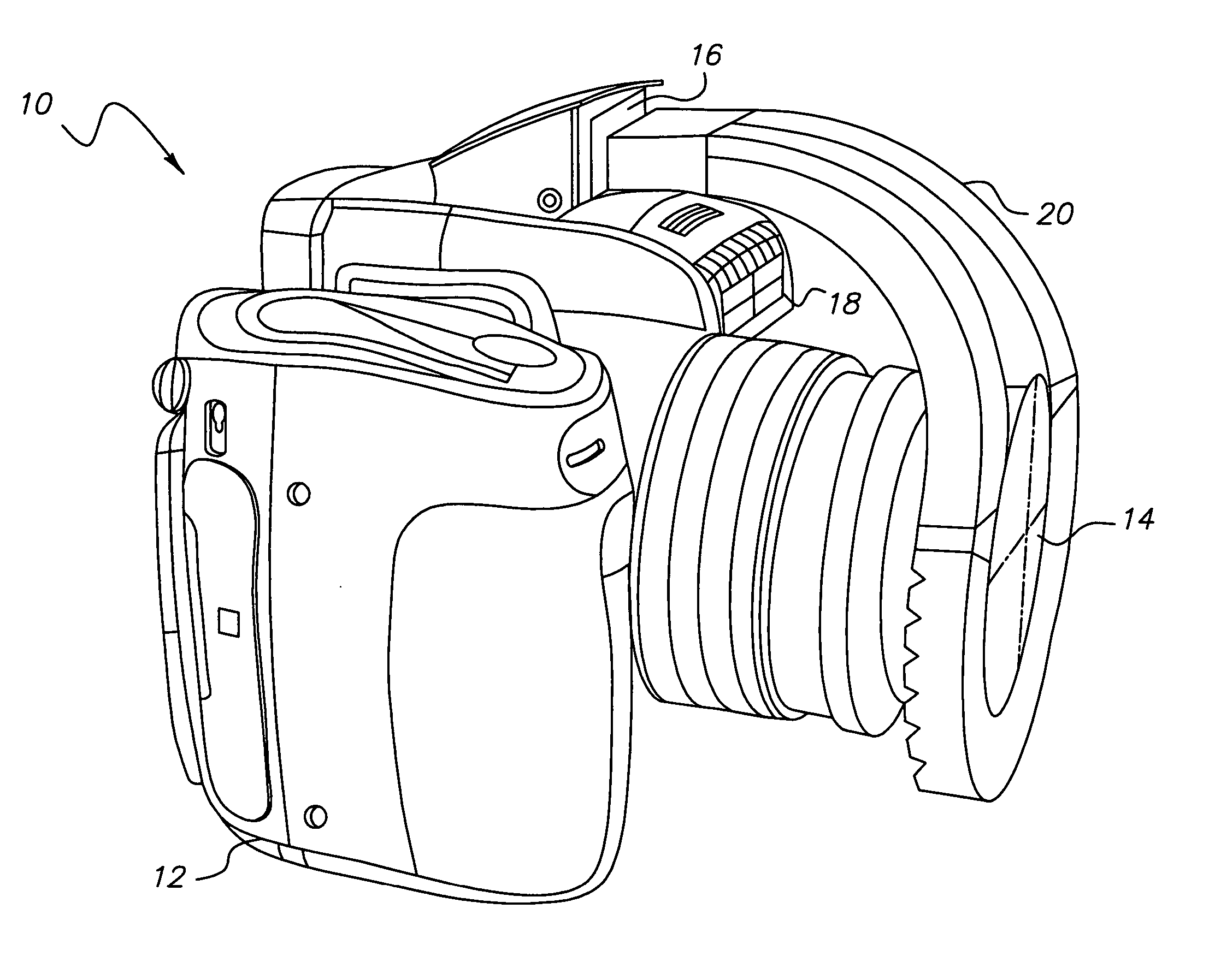
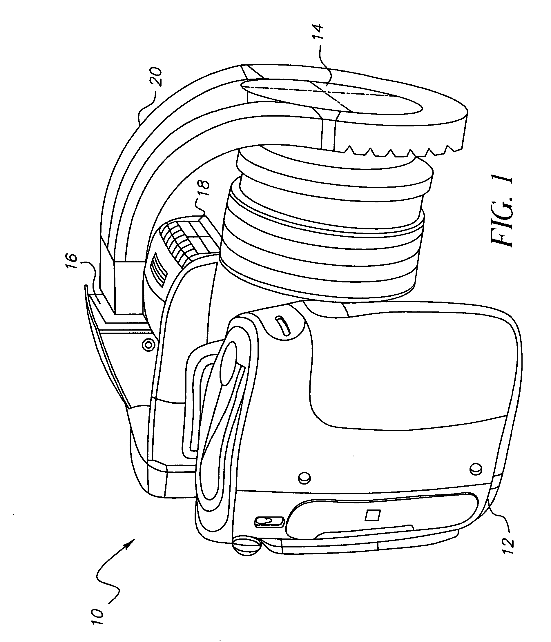
[0034] Referring now to FIG. 1 an image capture system for close up imaging is referred to in general by numeral 10. Image capture system 10 comprises a camera 12 having an attached ring light guide 20. Camera 12 has a close-up lens 14 that may be integral to camera 12 or may be a separable accessory. A flash unit 16 is preferably integral to camera 12 and may be built into the main body of camera 12 as a fixed-position device or may be a pop-up flash unit or other type of protruding flash unit. Alternately, flash unit 16 may be an accessory unit attached to camera 12 when needed. A light sensor 18 provides feedback on scene illumination and can be used to control flas...


PUM


Abstract

A ring illuminator (20) has a light channeling section (22) with an input face (24) optically coupling the light channeling section (22) to a flash unit (16) of a camera (12) for obtaining flash illumination therefrom. A ring section (26) is optically coupled to the light channeling section and extends around an aperture for fitting the ring illuminator around a lens (14). The ring section has a rear surface (30) for positioning toward the body of the camera. The rear surface has a plurality of light redirecting features (28) for redirecting at least a portion of the flash illumination from within the ring section outward from the camera, around the lens of the camera.

Description

FIELD OF THE INVENTION [0001] The present invention relates to an illumination apparatus for flash photography and more particularly to a ring light attachable to a camera for redistributing illumination from the camera flash unit. BACKGROUND OF THE INVENTION [0002] In conventional camera design, the flash illumination source of the camera is off-axis with respect to the objective lens of the camera and illuminates from one angular orientation only. While this may be acceptable for the bulk of imaging applications, this arrangement is particularly troublesome for close-up imaging, such as in dental imaging and imaging of small objects in near distance. In close-up camera work, the conventional flash illumination arrangement often results in undesirable shadow and overexposure effects. [0003] In response to the need for improved light distribution for minimizing shadows and other effects in close-up imaging, ring illumination has been developed. In ring illumination, a ring of light,...

Claims


Application Information

Patent Timeline
Patent Type & Authority Applications(United States)
IPC IPC(8): G03B15/03
CPCG02B6/0036G02B6/0038G03B2215/0539G03B15/05G02B6/0046
Inventor LEE, JUNWONHANSEN, STEVEN J.LIANG, RONGGUANG
Owner CARESTREAM HEALTH INC
Why Eureka
Try Eureka