Scan testable filter housing assembly for exhaust applications

a filter housing and exhaust technology, applied in the direction of filtration separation, separation processes, instruments, etc., can solve the problems of inaccessible, inability to access, and the downstream side of the filter is above the cleanroom ceiling, etc., to achieve the effect of reducing the risk of air entering the cleanroom to challenge the filter

Active Publication Date: 2006-03-02
CAMFIL USA
View PDF12 Cites 36 Cited by
  • Summary
  • Abstract
  • Description
  • Claims
  • Application Information

AI Technical Summary

Problems solved by technology

However, in filters used in exhaust applications, the downstream side of the filter is above the cleanroom ceiling, and is often not accessible.
Moreover, introducing aerosol within the cleanroom to challenge a filter is also undesirable.

Method used


Image

  • Scan testable filter housing assembly for exhaust applications
  • Scan testable filter housing assembly for exhaust applications
  • Scan testable filter housing assembly for exhaust applications

Examples


Embodiment Construction

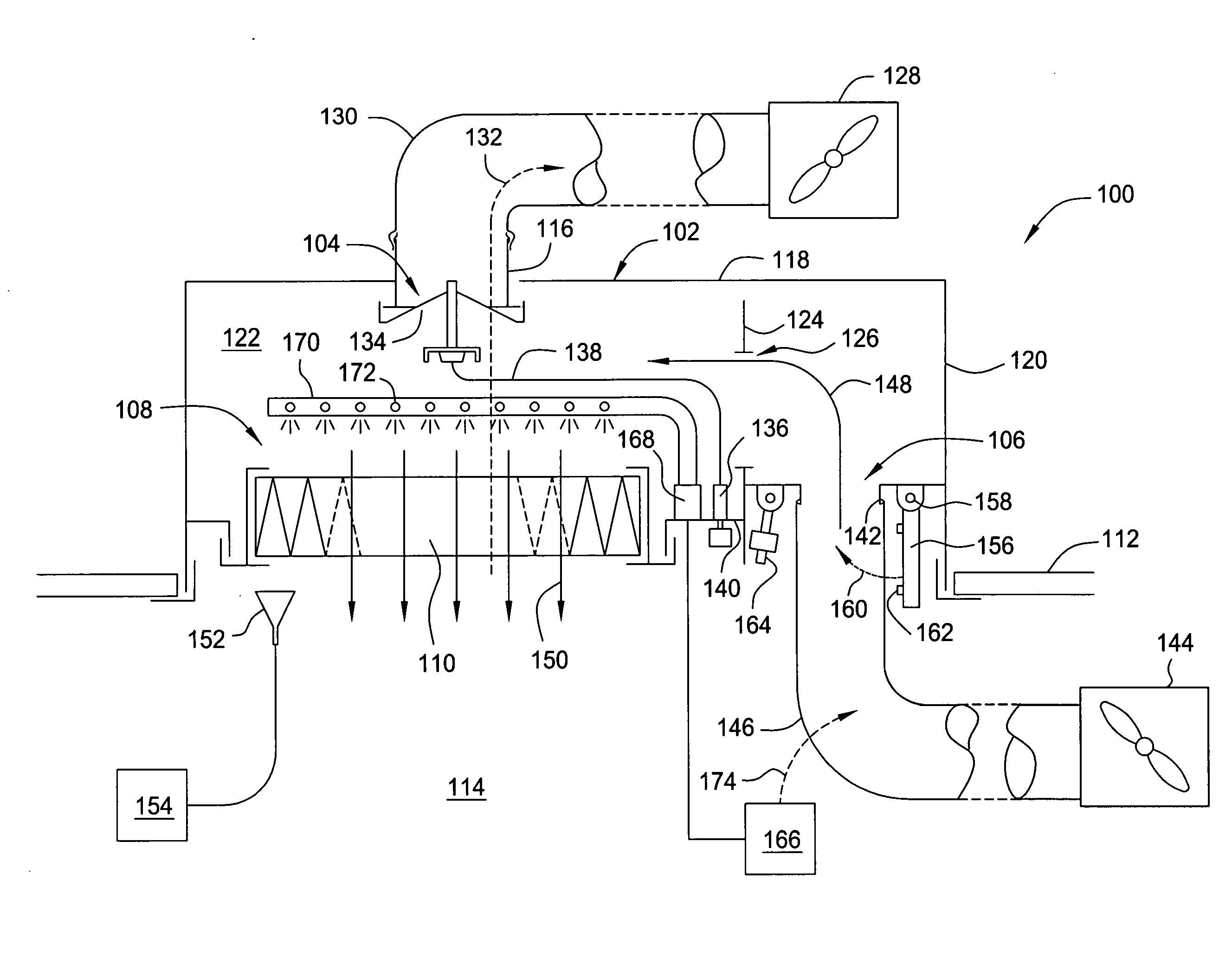
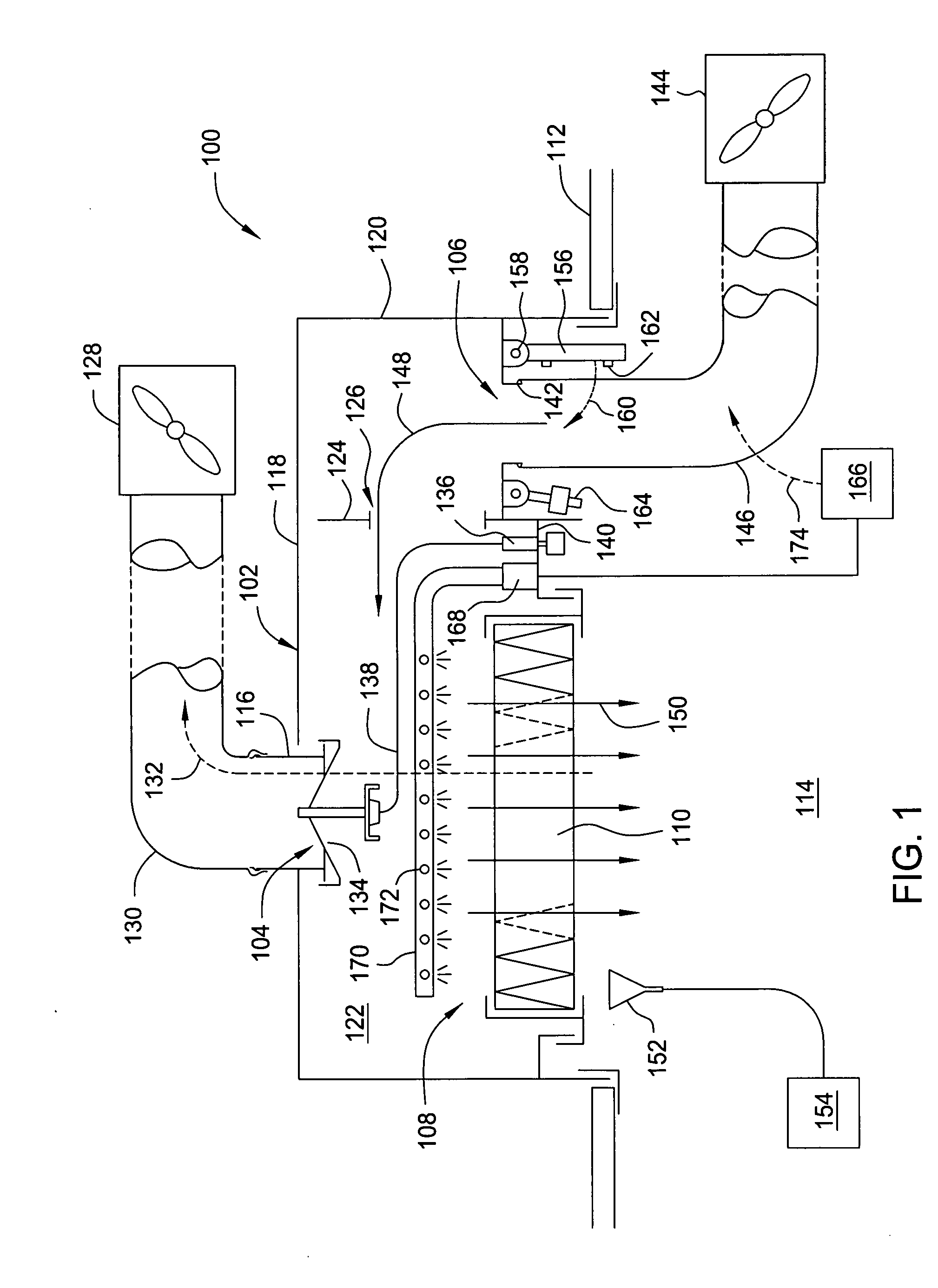
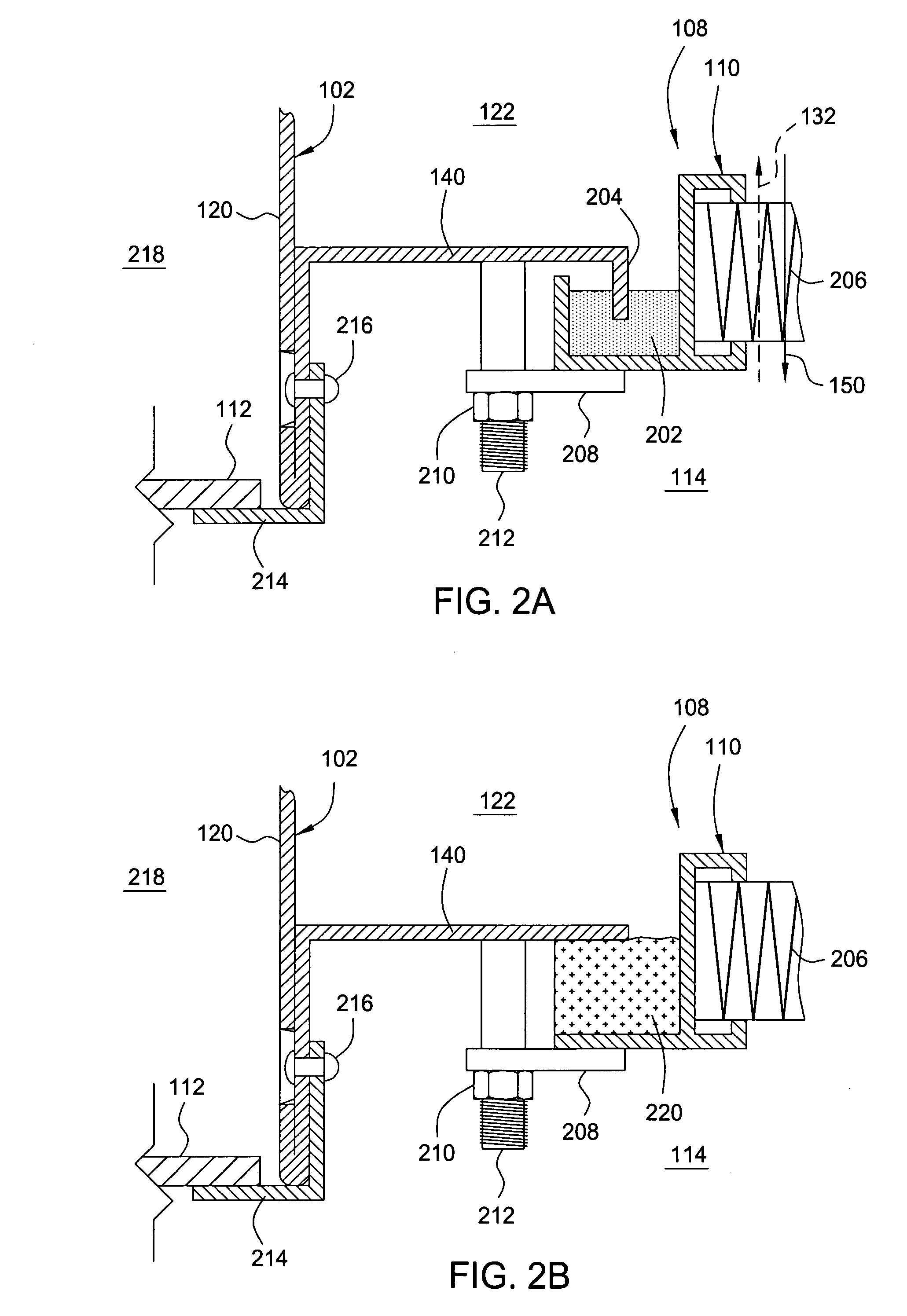
[0022]FIG. 1 depicts one embodiment of a filter housing assembly suitable for use in exhaust applications and having the capability to be scan tested in the reverse flow direction. The filter housing 100 includes a housing 102 configured to retain a filter element 110 in a structure, such as a sealing 112 of a cleanroom 114, mini environment or other suitable location. The housing 102 includes a first air flow port 104, a second air flow port 106 and a filter receiving aperture 108. In the embodiment depicted in FIG. 1, the first air flow port 104 is disposed opposite the filter receiving aperture 108. The second air flow port 106 is generally sized to deliver a flow, which when routed to the filter receiving aperture 108, is suitable for filter leak testing. Thus, the size of the second air flow port 106 is related to the filter receiving aperture 108 and performance properties of the filter element 110, and in one embodiment, second air flow port 106 is capable of providing at lea...


PUM

PropertyMeasurementUnit
velocityaaaaaaaaaa
face velocityaaaaaaaaaa

Abstract

A filter housing assembly for exhaust applications and method of testing the same is provided. In one embodiment, the filter housing assembly includes a housing having a filter receiving aperture, a first air flow port configured to couple the housing to an exhaust system and a second air flow port sized to deliver a flow capable of providing at least 75 feet per minute of air flow through the filter receiving aperture. A filter element is sealingly disposed in the filter receiving aperture of the housing. A cap is provided that operably seals the second air flow port when not in use. In another embodiment, a method for testing a filter housing assembly for exhaust applications includes providing air through a filter element disposed in the housing in a direction opposite an operational air flow direction, leak testing the filter element from a roomside of the filter element, and, flowing air through the filter element after leak testing in the operational direction.

Description

CROSS-REFERENCE TO RELATED APPLICATIONS [0001] This application claims the benefit of U.S. Patent Provisional Application Ser. No. 60 / 598,627, filed Aug. 4, 2004, which is herein incorporated by reference in its entirety.BACKGROUND OF THE DISCLOSURE [0002] 1. Field of the Invention [0003] The embodiments of the present invention relate generally to a filter housing assembly for exhaust applications and leak testing thereof. [0004] 2. Background of the Invention [0005] Cleanrooms are utilized in many industries for contamination control and to improve product yields. A plurality of filters, typically mounted in the ceiling of the cleanroom, are configured to remove particulates from air entering and / or exhausted the cleanroom at a predetermined efficiency selected based upon the cleanliness requirements of the activities performed in the cleanroom. As particulates load the filtration media disposed in the filter, the airflow through the filter decreases as the pressure drop across th...

Claims


Application Information

Patent Timeline
Patent Type & Authority Applications(United States)
IPC IPC(8): G01M3/26B01D35/30
CPCG01M3/3281B01D2273/18
Inventor MORSE, THOMAS C.HUZA, MARK
Owner CAMFIL USA
Why Eureka
Try Eureka